Programming, Installation, A. wiring – Flowline XP89 EchoSafe User Manual
Page 8: A. fitting selection, Opening the enclosure
.
PROGRAMMING
Step Twelve
A. Fitting Selection:
Check the transmitter part
number to determine the required 2” fitting thread
type. The transmitter is commonly installed in tank
adapters, flanges, brackets or stand pipes.
1. Adapter:
Select a tank adapter fitting with
minimal height so as to ensure that the
installed transducer will not be substantially
elevated into the fitting. Avoid tank adapter
styles with threads and/or pipe stops forward
of the installed transducer.
2. Flange:
Tall flanges with narrow risers
impede the acoustic signal. Select a fit-
ting with the right riser height versus inner
diameter geometry. The transmitter may be
elevated up to 12” (30 cm) in a 6” (15 cm)
riser, 8” (20 cm) in a 4” (10 cm) riser and 3”
(7.6 cm) in a 2” (5 cm) riser.
3. Bracket:
The LM50-1001 bracket or equiva-
lent can be used for open tank top installa-
tions against the side wall.
4. Stand Pipe:
A stand pipe may be
used to dampen turbulence or separate
surface foam. Select a minimum 3”
pipe for the stand pipe. The pipe length
should run the measurement span. Cut a
45° notch at the bottom of the pipe and
drill a 1/4” pressure equalization hole in
the dead band.
Ec
ho
Sa
fe
EchoSafe
EchoSafe
VACUUM
EchoSafe
Do not install at
angle relative
to the liquid
Do not install
within 3” of
tank side wall
Do not install
with objects
in the beam
Do not install
in applications
with vacuum
EchoSafe
Dead Band
Ventilation
Hole
Operational Range
Highest
Liquid Level
Lowest
Liquid Level
3" Minimum
Diameter
EchoSafe
Warning
Flowline Ultrasonic transmitters have been optimized for use
in non-metallic fittings. For best performance, avoid the use
of metal fittings.
Install the appropriate installation fitting. Make sure that the
fitting and transmitter threads are not damaged or worn. Hand
tighten the transmitter within the fitting. Perform an installed
leak test under normal process conditions prior to system start
up.
EchoSafe
EchoSafe
Height
Inner Diameter
Adapter
Flange
Stand Pipe
Bracket
EchoSafe
Gasket
Riser
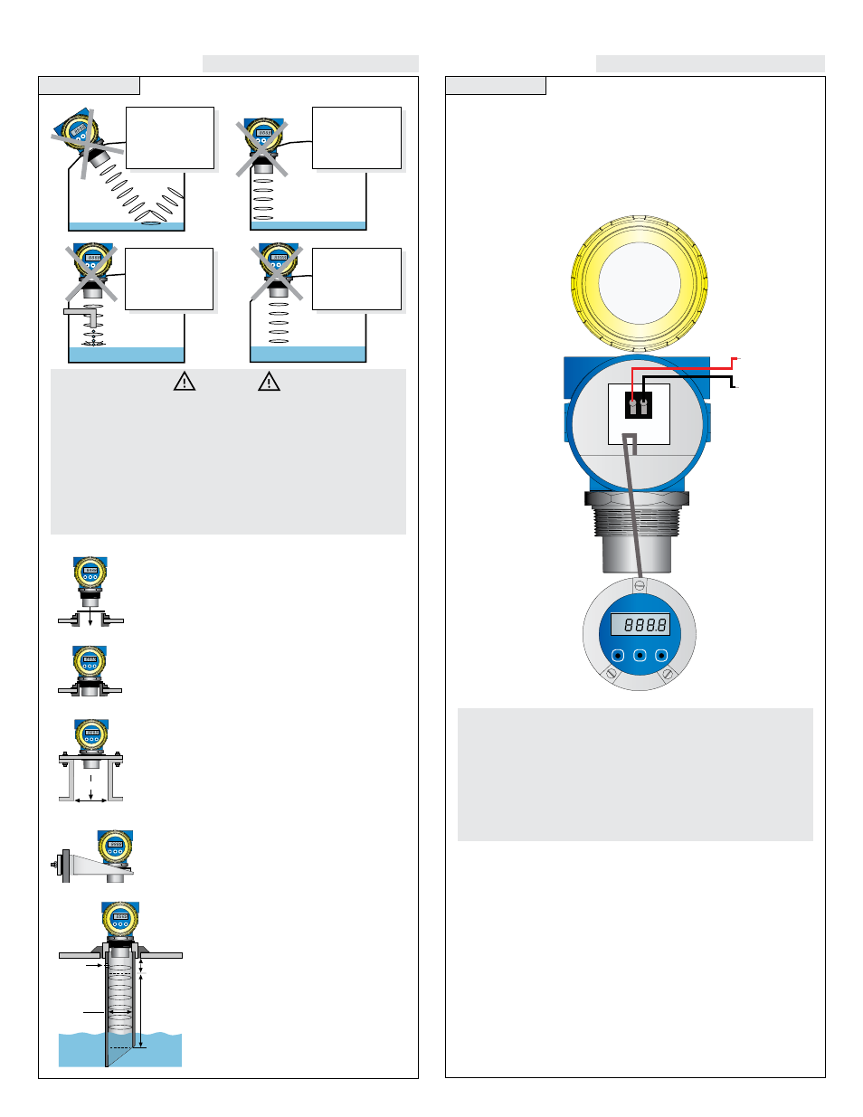
INSTALLATION
Step Thirteen
(+)
(-)
24 VDC
1
2
(FKR6DIH
Ù
A. Wiring:
A supply voltage of 18 - 28 VDC is used to power the
XP8_ series. The sensor circuit should never exceed a maximum of
28 volts DC. Electrical wiring of the sensor should be performed in
accordance with all applicable national, state, and local codes.
Opening The Enclosure:
EchoSafe is designed to be installed
in a hazardous areas and, when installed, do not open the unit
while power is applied. Always disconnect the power source from
EchoSafe prior to opening, programming, installing, or removing it.
Additionally, ensure that electrical wiring, fittings and mechanical
connections conform to all applicable electrical codes.