Preparation, Menu items – Flowline XP89 EchoSafe User Manual
Page 4
Step Four
PREPARATION
A. Supply Voltage:
The transmitter power supply voltage should
never exceed a maximum of 28 VDC. Flowline controllers and
meters have built-in 24 VDC power supplies for use with the trans-
mitter. Alternative controllers and/or power supplies with a minimum
output of 18 VDC may also be used with the transmitter for calibra-
tion and/or operation.
B. Factory Span:
All transmit-
ter models are factory calibrated with
4 mA at their maximum range (tank
empty) and 20 mA at their minimum
range (tank full). The 4 and 20 mA
span set points can be reverse cali-
brated on all models.
C. Maximum Applied Range:
The Individual or cumulative
effects of agitation or vapor can reduce the overall quality of signal
return and shorten the maximum applied range of the transmitter.
To determine the maximum applied range of the transmitter in your
application, refer to the below de-rating chart.
50Khz
0
1
2
3
4
5
6
7
8
9
10
0%
50%
100%
Ultrasonic Derating Chart
LU12-5__1
LU13-5__1 & LU14-5__1
Agitation = 1 - 5 @100Khz
Agitation = 1 - 7 @50Khz
Temp
= 3 @100Khz
Temp
= 3 @50Khz
Foaming = 4 - 6 @100Khz
Foaming = 7 - 9 @50Khz
Solids
= 5 - 6 @100Khz
Solids
= 7.5 @50Khz
Maximum Applied Range De-rating Chart
XP88/89-0
Agitation = 1-3 @ 50 kHz
Vapor
= 3-5 @ 50 kHz
Step Five
MENU ITEMS
A. WARM UP:
This is the initial power up mode. When this mes-
sage is displayed, the transmitter is going through its power up rou-
tine, and validating the target value. After a short period of time, this
message will disappear and be replaced by a numeric value.
B. FULL:
Level has reached the programmed FULL set point.
C. EMPTY:
Level has reached the programmed EMPTY set point
D. UNITS:
Selectable in inches centimeters, feet, meter or percent.
The factory default is Inches.
E. INCHES:
Inch units of measurement.
F. CM:
Centimeters units of measurement.
G. FEET:
Feet units of measurement.
H. METERS:
Meter units of measurement.
I. PERCNT:
0-100% units of measurement. Percent is the calcu-
lated value based on the 4mA and 20mA set points.
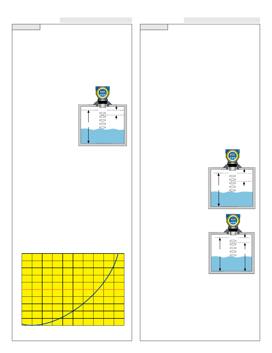
J. TANK:
Menu through which the
4-20 mA span is adjusted.
K. HEIGHT:
The point in inches,
feet, meters, or centimeters from the
transducer face where the output will
be 4 mA (generally the bottom of the
tank). Factory default is the same as
the unit’s maximum range. Example:
XP88 = 295” maximum range which
is also the same 4 mA set point under
factory default.
L. Fill H (Fill Height):
The point
in inches, feet, meters or centimeters
from the bottom of the tank to the
high level where the output will be
20 mA (generally the straight wall
distance from the bottom of the tank).
NOTE: The transmitter dead band
is automatically subtracted from the
FILL H. Example: XP88 = 8” dead
band. Therefore the maximum FILL
H is 295” [maximum range] - 8”
[dead band] = 287”.
M. REV mA (Reverse mA):
Allows the user to select 20 mA at
the bottom and 4 mA at the top of the tank (20-4 mA). Factory default
is 4 mA (MaxR) at the bottom and 20 mA (MinR) at the top.
N. NORM:
Sets EchoSafe so 4 mA is at the bottom of the tank and
20 mA at the top. This is the default settings.
O. REV:
Sets EchoSafe so 20 mA is at the bottom of the tank and
4 mA at the top.
EchoSafe
™
EchoSafe
™
HEIGHT
(MaxR)
EMPTY
FULL
FILL H
(MinR)
EchoSafe
™
EchoSafe
™
HEIGHT
(MaxR)
EMPTY
FULL
FILL H
(MinR)
EchoSafe
™
EchoSafe
™
4 mA
20 mA
20 mA
4 mA
XP89-0
Reverse Mode