Installation, Minimum range (minr) setting, Maximum application range – Flowline LU20 EchoTouch User Manual
Page 5: Echo attenuation graph, Minr, Step six step seven
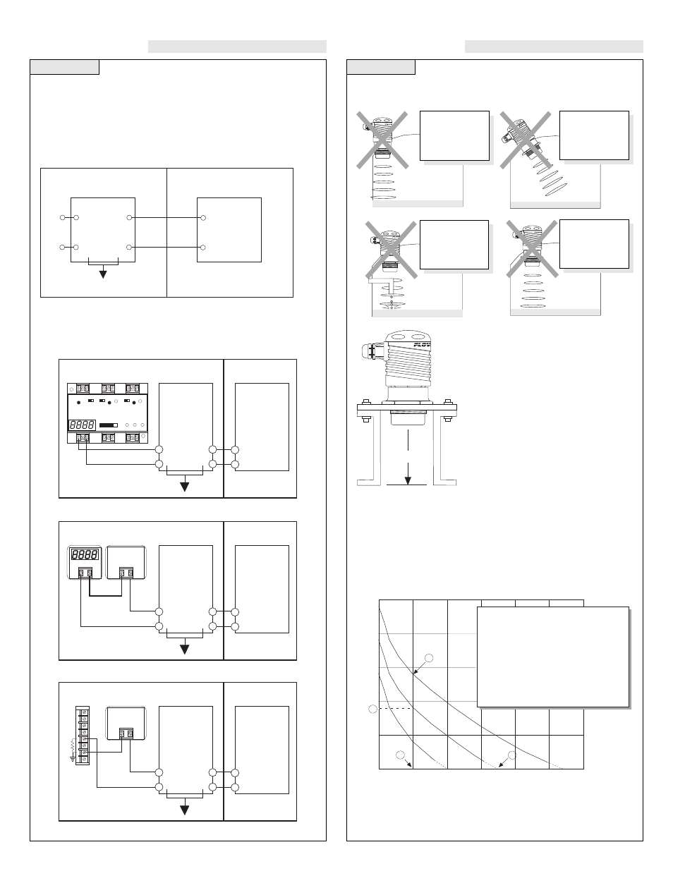
Step Six
Step Seven
INSTALLATION
INSTALLATION
Minimum Range (MINR) Setting
If installing the LU20 in a flange or any
device which recesses the bottom of the
transmitter, use the MINR setting. The
minimum value for the MINR setting is
the distance from the bottom of the trans-
mitter to the end of the flange. Never set
MINR to less than 6.0 inches.
Mounting the LU20 is critical to the successful operation of the trans-
mitter. Avoid the following parameters:
Maximum Application Range
The maximum range of LU20 is 18 feet at 110 dB. Under less than
ideal conditions, a number of factors can reduce the overall quality of
signal return and shorten the accurate range of the transmitter. To
determine the maximum application range of the product, follow the
signal return formula against the echo attenuation graph below.
Echo Attenuation Graph
TYPICAL
CUR
VE
10 dB
ABSORPTION
20 dB
ABSORPTION
ALIGN READING (dB)
10
20
30
40
50
40
80
120
160
200
240
00
DISTANCE FROM FACE OF TRANSDUCER (inches)
4
1
3
2
1: Distance from transducer = 40"
2: Highest possible ALIN = 28dB
(under ideal conditions)
Adjust mechanical alignment of unit
to maximize displayed ALIN value
• PREDICT MAXIMUM RANGE
USING ALIGN VALUE
3: If the actual ALIN = 18dB at D = 40"
4: Maximum Range = 138"
EXAMPLE:
• OPTIMIZE ALIGNMENT
MINR
VACUUM
Avoid
Interference
from side of
tank
Do not install
LU20 at
an angle
Avoid Inter-
ference from
obstructions
in tank
LU20 will not
operate in
vacuum
The LU20-50_1-IS requires 12-32 VDC power with at least 25 mA
supply in order to operate. The follow provides an overview of wiring
the LU20-50_1-IS to various devices. Please note that a barrier must
be installed between the Echotouch and the device and the barrier
must be located within the nonhazardous location.
1. Hazardous System Diagram
2. Wiring to a Flowline Continuous Controller
3. Wiring to a Two-Wire Loop Indicator
4. Wiring to a PLC
NON-HAZARDOUS
LOCATION
Model LU20
Ultrasonic
Level
Transmitter
Vmax = 32.0 V
Imax = 130 mA
Ci
≈
0
µ
F
Li
≈
0
µ
H
Any Approved
I.S. Barrier
Vdc
≤
32.0 V
Isc
≤
130 mA
Ca
≥
0
µ
F
La
≥
0
µ
H
HAZARDOUS
LOCATION
+
-
+
-
See LC52 manual for
jumper settings
LATCH
ON OFF
P W R
R E L AY 1
INVERT
DELAY
R E L AY 2
INVERT
DELAY
4
20
OP
E A S Y CAL
UP
DOWN SET
INPUT
0%
100%
OFF SET
SP
AN
RL
Y1
RL
Y2A
RL
Y2B
NON-HAZARDOUS LOCATION
Control drawing for the LU20-5001-IS ultrasonic level transmitter
approved under the entity concept as an I.S. apparatus
Control Drawing: LU20CD
Rev. 7-24-97
Model LU20
Ultrasonic
Level Transmitter
Vmax = 32.0 V
Imax = 130 mA
Ci
≈
0
µ
F
Li
≈
0
µ
H
Any Approved
I.S. Barrier
Vdc
≤
32.0 V
Isc
≤
130 mA
Ca
≥
0
µ
F
La
≥
0
µ
H
Supply
HAZARDOUS LOCATION
Class I, Div I, Groups A, B, C & D
+
-
NON-HAZARDOUS
LOCATION
Model LU20
Ultrasonic
Level
Transmitter
Vmax = 32.0 V
Imax = 130 mA
Ci
≈
0
µ
F
Li
≈
0
µ
H
Any Approved
I.S. Barrier
Vdc
≤
32.0 V
Isc
≤
130 mA
Ca
≥
0
µ
F
La
≥
0
µ
H
HAZARDOUS
LOCATION
+
-
+
-
-
+
DC Power
Supply
14-32 VDC
T
ypical PLC
6
5
4
3
2
1
0
A
250
Ω
NON-HAZARDOUS
LOCATION
Model LU20
Ultrasonic
Level
Transmitter
Vmax = 32.0 V
Imax = 130 mA
Ci
≈
0
µ
F
Li
≈
0
µ
H
Any Approved
I.S. Barrier
Vdc
≤
32.0 V
Isc
≤
130 mA
Ca
≥
0
µ
F
La
≥
0
µ
H
HAZARDOUS
LOCATION
+
-
+
-
-
+
DC Power
Supply
14-32 VDC