Specifications, Technology, Warning – Flowline LU20 EchoTouch User Manual
Page 2: Part# description thread
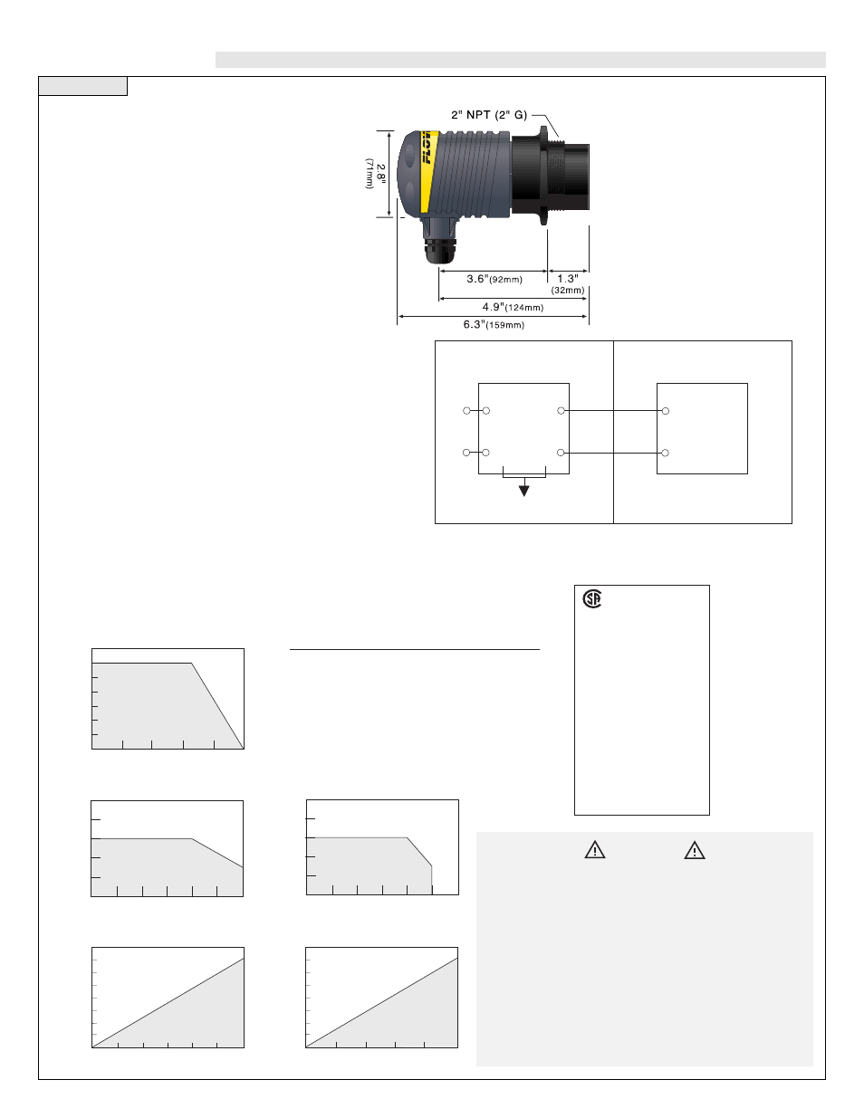
Step One
SPECIFICATIONS
Range:
0.5 to 18 feet (15 cm to 5.4 m)
Accuracy:
± 0.25% of span in air
Resolution:
0.125” (3 mm)
Frequency:
50 kHz
Pulse rate:
2 pulses per second
Beam width:
8° conical
Deadband:
0.5’ (15 cm) minimum
Blocking distance:
0.5 to 18 feet (15 cm to 5.4 m)
Display type:
4 segment LCD
Display units:
Inch (cm)
Memory:
Non-volatile
Supply voltage:
GP:
12-36 VDC
IS:
12-32 VDC
Max loop resistance GP:
900 Ohms @ 36 VDC (see below)
IS:
900 Ohms @ 32 VDC (see below)
Signal output:
GP:
4-20 mA, 12-36 VDC (see below)
IS:
4-20 mA, 12-32 VDC (see below)
Signal invert:
4-20 mA / 20-4 mA
Calibration:
Push button
Fail-safe diagnostics: Reverts to 4 mA, 22 mA or remains constant
Temperature rating:
F: -40º to 140º C: -40º to 60º (see below)
Temp. compensation: Automatic over entire range
Pressure rating:
30 psi (2 bar) @ 25 °C., derated @ 1.667 psi
(.113 bar) per °C. above 25 °C. (see below)
Enclosure rating:
NEMA 4X (IP65)
Enclosure material:
Polypropylene (PP), U.L. 94VO
Transducer material: Polyvinylidene Fluoride (PVDF)
Mounting threads:
2” NPT (2” G)
Mounting gasket:
Viton (2”) metric only
Conduit connection: 1/2” NPT (1/2” BSP)
CE Compliance:
EN 50082-2 immunity
EN 55011 emission
CSA Certificate:
LR79326-10
*GP = General Purpose
IS Intrinsically Safe
Technology
An ultrasonic sound wave is pulsed two
times per second from the base of the
transducer. The sound wave reflects
against the process medium below and
returns to the transducer. The micro-
processor based electronics measure
the time of flight between the sound
generation and receipt, and translates
this figure into the distance between the
transmitter and process medium below.
Warning
The LU20 is a loop powered device. The load should never
exceed 900 Ohms.
LU20-50_1-IS must be installed in accordance with drawing
LU20CD rev B (see steps) for safe operation in a hazardous
area.
When installing the LU20, never tighten the transmitter from
the body. Always use the wrench flat located above the
threads.
Always install the 2” Viton gasket with the LU20-5061 and
the LU20-5061-IS. The G threaded version of the Echotouch
will not seal unless the gasket is installed properly.
NON-HAZARDOUS LOCATION
Control drawing for the LU20-5001-IS ultrasonic level transmitter
approved under the entity concept as an I.S. apparatus
Control Drawing: LU20CD
Rev. 7-24-97
Model LU20
Ultrasonic
Level Transmitter
Vmax = 32.0 V
Imax = 130 mA
Ci
≈
0
µ
F
Li
≈
0
µ
H
Any Approved
I.S. Barrier
Vdc
≤
32.0 V
Isc
≤
130 mA
Ca
≥
0
µ
F
La
≥
0
µ
H
Supply
HAZARDOUS LOCATION
Class I, Div I, Groups A, B, C & D
LR79326-10
NRTL/C
®
Intrinsically Safe/
Securite Intrinseque
Exia
For use in
Hazardous Locations:
Class I, Groups A, B, C & D
Class II, Groups E, F & G
Class III
Temperature Code: T3C
Intrinsically Safe when used with
an approved I.S. barrier. Entity
Parameters
V
max
= 32.0 VDC
I
max
= 130 mA
C
i
= 0
µ
F
L
i
= 0
µ
H
Warning: Suitable for Class I, Groups A, B,
C & D; Class II, Groups E, F & G; Class III,
T3C; when used with an approved I.S.
barrier. Substitution of components may
impair intrinsic safety LU20-50X1-IS
requirements for Intrinsically Safe
operation
Temperature/Pressure Derating
35
30
25
20
15
10
05
00
-40 -20 00 20 40 60
Operating Pressure (psi)
Temperature (
°
C)
Unacceptable
Range
Acceptable
Range
Maximum Temperature/Voltage Derating
Continuous 20 mA Curve (LU20-50_1)
100
80
60
40
20
0
Operating Voltage (VDC)
Ambient Sensor
T
emperature (
°
C)
Unacceptable
Range
Acceptable
Range
12 16 20 24 28 32 36
1,000
750
500
250
0
Max. Series Resistance (Ohms)
12 16 20 24 28 32 36
Supply Volyage (VDC)
Unacceptable
Range
Acceptable
Range
Flowline 4 or 20 mA
LU20-50_1 Electrical Loading Limits
Maximum Temperature/Voltage Derating
Continuous 20 mA Curve (LU20-50_1-IS)
100
80
60
40
20
0
12 16 20 24 28 32 36
Operating Voltage (VDC)
Ambient Sensor
T
emperature (
°
C)
Unacceptable
Range
Acceptable
Range
1,000
750
500
250
0
Max. Series Resistance (Ohms)
12 16 20 24 28 32
Supply Volyage (VDC)
Unacceptable
Range
Acceptable
Range
Flowline 4 or 20 mA
LU20-50_1-IS Electrical Loading Limits
Part#
Description
Thread
LU20-5001
General Purpose
2” NPT
LU20-5061
General Purpose
2” G
LU20-5001-IS
Intrinsically Safe
2” NPT
LU20-5061-IS
Intrinsically Safe
2” G