Flowline LU27 EchoSonic II User Manual
Page 10
10
Wiring the EchoSonic® II
After mounting the sensor, make the necessary electrical connections. A wiring diagram
with specific recommendations for the sensor’s configuration can be printed from the
WebCal program. A typical wiring diagram is shown on the next page.
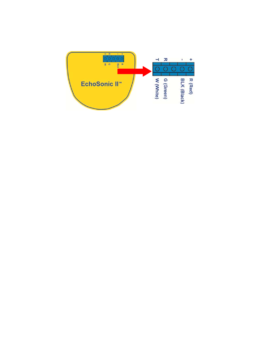
Red (Power) and Black (Return) leads are for connection to a 24 VDC power supply or to
a 4‐20 mA loop power source. The red and black wires can be extended more than 1000
feet using 22‐gauge or larger wire, however do not extend the green and white wires.
White (Tx) and Green (Rx) leads are reserved for use with WebCal and should not be
connected during usage in the application. These wires should not be connected to
WebCal while power is supplied from any source other than the LI99‐1001 Fob.
Never allow the white or green wires to touch any power supply.