10 repair kits and accessories, 900 series digital meters w / pulser, Electrical installation information – Fill-Rite 900D Series Digital Liquid Meter User Manual
Page 10
10
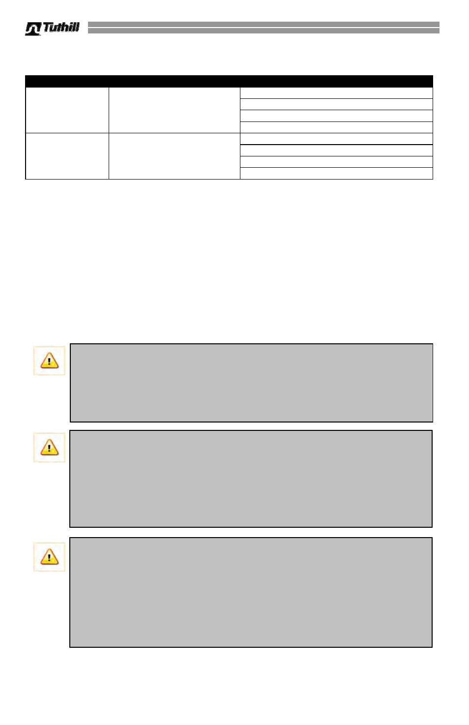
Repair Kits and Accessories
Kit #
Description
Contents
901DPMK300V
900 Series Meter (gallons)
with Inlet Flange for FR300
& FR700 Pumps
900 Series Meter (gallons)
Inlet Flange (4-hole)
Required O-rings
Required Fasteners
901DPLMK300V
900 Series Meter (liters)
with Inlet Flange for FR300
& FR700 Pumps
900 Series Meter (liters)
Inlet Flange (4-hole)
Required O-rings
Required Fasteners
900 Series Digital Meters w / Pulser
Certain 900 Series Digital Meters (model number suffix of DP) can be powered externally and
are equipped with an integral electronic pulser uni t for use with Fuel Management Systems.
The Fuel Management System must be configured for current sinking or contact closure types
of signals. The meter provides ten counts per unit of measure (in gallon, liter, and quart units of
measure only; pulser does not operate in ounce, pint, or user specific units of measure).
Electrical Installation Information
There are multiple electrical configurations for the 900D Series Digital Meter, featuring two
different power sources. It is critical that the meter be installed and wired correctly to ensure
correct, safe operation.
WARNING! Electrical wiring should be performed ONLY by a licensed electrician
in compliance with local, state, and national electrical codes (NEC/ANSI/NFPA 70,
NFPA30, and NFPA 30A in US installations for example), as appropriate to the
intended use of the meter.
The barrier must be properly connected to an earth
grounded. Improper installation of this meter and barrier can result in equipment
failure or damage, serious bodily injury, or death!
CAUTION! For meter installations using external power, the power should come
from a dedicated circuit. No other equipment should be powered by this circuit.
Wiring must be of sufficient size to carry the correct current for the meter. Voltage
drop will vary with distance to meter and size of wire; refer to the National
Electrical Code (NEC), or local codes, for Voltage Drop Compensation to be sure
you are using the correct size wire for your application. Wiring between the
barrier and meter
MUST NOT exceed 850’. Refer to “Typical Installation” wiring
information document DC000675-010 (included in the meter box) for details.
IMPORTANT! Explosion Proof versus Intrinsically Safe:
There is a distinct difference between a product that is “Explosion Proof” versus a
product that is “Intrinsically Safe”. Intrinsically Safe products are built so they do
not generate enough heat or energy to cause ignition or explosion. They are safe
to use in an explosive atmosphere (i.e.: around fuel tanks, etc. where explosive
vapors may be present). An Explosion Proof product is one that is designed to
contain an explosion internally if one should occur. Understanding the difference
between the two is critical when installing a new item to be certain the installation
is safe and to code.