Part 4 - configuration and operation – Dynasonics D7700 Series Insertion Doppler Ultrasonic Flow Meter User Manual
Page 26
Rev. 2/00
-4.3-
77X
B. Totalizer Calibration — Series D7701
1. If an oscilloscope or signal counter is available, a
signal from test point TP10 will show the totalizer
count rate at a particular flow. Refer to the drawing in
the Appendix titled 091-1048-102 Series 300
Waveforms. The pulse rate at TP10 can be x 10, x
100, x 1000 or x10,000 of totalizer count rate, at the
CTR output on terminal strip. For example, if the
pulse rate is 200 milliseconds (multiplier switch SW 1
programmed for 100), then the counter rate at CTR
terminals will be scaled to provide a count every 20
seconds. The total counter output (CTR) range can
be adjusted from approximately 0.5 to 5 seconds with
a full scale flow indication.
Totalizer Adjustment:
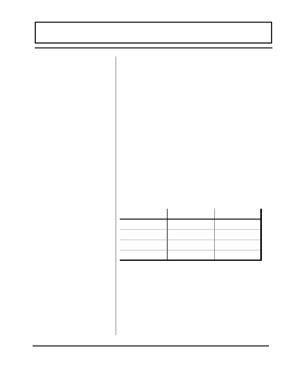
(CTR CAL) - (pot R90 and DIP SW 1). The multiplier
DIP switch SW 1 may be programmed as follows:
SW 1 Position
If an oscilloscope or signal counter is not available,
then use the following procedure. The Pot R90 has a
range of 0.5 to 5 seconds. SW1 is then used to
increase this rate all the way up to 50 minutes.
2. Stopwatch Procedure - with a known flow rate
established on the flow meter digital display, time the
count rate on the totalizer by a stopwatch, measuring
the time between totalizer counts. If the totalizer is
reading lower than desired, turn CTR, CAL pot R90
PART 4 - CONFIGURATION AND OPERATION
SW1-1
SW1-2
MULTIPLIER
OFF
OFF
X 10
ON
OFF
X 100
OFF
ON
X 1000
ON
ON
X 10000