Dynasonics D7700 Series Insertion Doppler Ultrasonic Flow Meter User Manual
Page 22
Rev. 2/00
-3.4-
77X
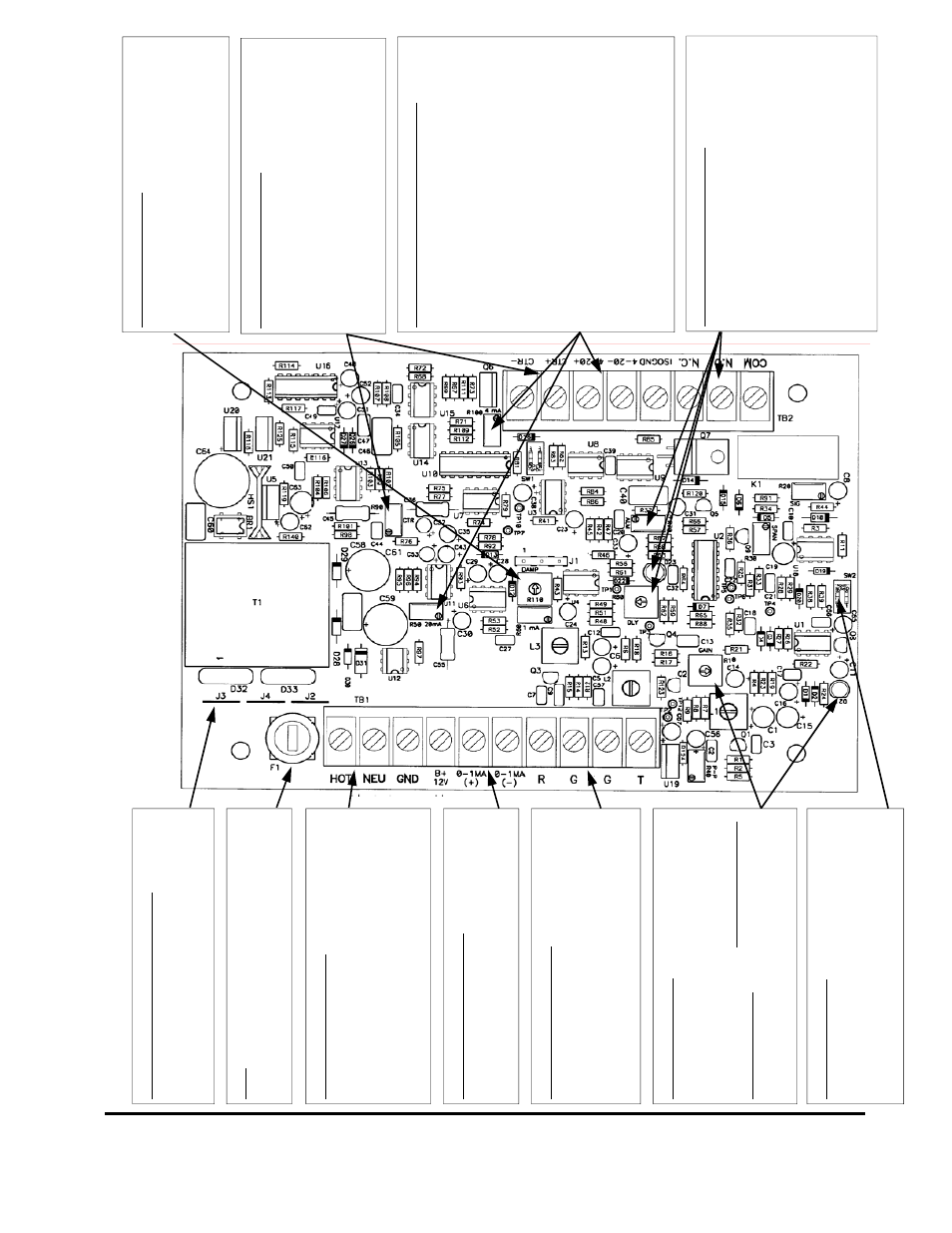
Figure 2.2 D7700 Operated with 1
15/230 V
AC Power Suppl
y
02/02/200
0
R110 [DAMP] Control
Adjust R110 [DAMP] to st
abilize flo
w
rate and
output rea
d
in
g
s
. Adjust CCW
to increase th
e
response of the instru
ment; adjust CW to de-
crease res
pon
se time (smoot
h the disp
la
y
read
ings a
nd o
u
tputs).
CT
R Output C
onn
ectio
n
s
T
he C
T
R output is desig
ne
d to oper
ate both
electro
n
ic an
d
electrom
echa
ni
cal totaliz
ers.
T
he output can
drive lo
ads as
lo
w
as 9
0
ohms. Control
R90 [CT
R
] adjusts the span o
f
this output. Sw
itc
h
set SW
1 controls the CT
R
output b
y
facto
rs of X10. See
details i
n
the
manu
al descr
ib
ing CT
R adjust
m
ent.
Iso
lat
ed
4-
20m
A Outp
ut C
o
n
n
e
ct
io
ns
Ther
e
are
tw
o metho
d
s
to
c
o
n
n
e
c
t t
h
is
o
u
tput
:
•
Whe
n t
he
D30
0
/D30
1
i
s
pow
er
ed f
rom AC
pow
er s
our
c
e
s
, 24
Vd
c o
f i
s
o
la
ted
pow
er
is
a
v
ai
la
ble
at
t
he
4-2
0
mA+ t
e
rm
ina
l. S
im-
ply
conne
ct
ing
t
he t
a
rg
et
’s
(c
ha
rt re
co
rde
r,
dat
a l
o
g
ger,
AD
C) 4-
20mA+
an
d 4-
20mA
–
inp
u
ts
t
o
t
h
e
s
e
tw
o out
put
term
ina
ls
w
ill
dri
v
e
4-2
0
mA t
h
rou
g
h
10
00
o
h
ms.
•
If th
e t
a
rg
et
’s
in
tern
al D
C
p
o
w
e
r sour
ce
is
uti
liz
ed
to
p
o
w
e
r th
e 4-
20mA
lo
op,
Co
n-
ne
ct t
he
ISOG
ND term
ina
l t
o
t
he t
a
rg
et
’s
grou
nd
an
d t
h
e
tar
get
’s
4-
20m
A in
put
to
th
e
4
-20
mA–
te
rm
in
al
.
Contr
o
l
R10
0
[
4
mA] i
s
us
ed
to
ad
ju
st
4mA
off
s
et
an
d R
50
[20mA]
to
ad
ju
s
t 20mA
s
p
a
n
.
Flow
Rate Relay
Connections
The D
300/D
3
0
1
is equip
ped w
ith a flo
w
rate
control rela
y
.
The rela
y
is designed to c
ontrol
loads to 2
50 Va
c and 1
0
A.
T
h
e rela
y
activates
w
hen the flo
w
rate is less tha
n
the set point.
Ac
tiv
a
tion is
indic
a
ted b
y
D23 [LED]. The relay
setpoint is c
ontr
o
lled b
y
adjusting R70 [A
LM]
there is also a
alarm del
a
y
feature that requires
the alarm co
ndi
tion to be
prese
n
t for a period of
time before rela
y
activation. T
h
e dela
y
can be
increa
sed b
y
a
d
justing R
80 [D
ELA
Y
] CW.
Po
w
e
r Su
ppl
y
Jumper Pl
ace
m
ent
115 Vac
J2 and J3
onl
y
230
Vac
J4
onl
y
12-24 Vdc
Does not matter
Fu
se
115/2
30 Vac
1/16A 3AG
Dela
y
Acti
on
AC Po
w
e
r Connections
115/2
30 Vac 5
0
/60 Hz cle
an
AC po
w
e
r re-
quir
ed. Do not
connect in
par
alle
l
w
ith circ
uit
s
oper
ating fl
ore
scent lig
ht
in
g, valves, contro
l
rela
ys, VF
Ds, etc. GND connectio
n
is op-
tiona
l. If
GND is connecte
d, verif
y
th
at it is at
the same pot
e
n
tial as the
pip
ing s
y
stem.
0-1 mA Output Con
nectio
n
T
h
is output is desig
ned to dr
iv
e loa
d
s up to
150
0 ohms. Use R60 [1mA] control to ad
jus
t
span.
T
ransducer Co
nnecti
ons
Con
nect the fo
ur
w
ires from the t
w
o coa
x
ial
cabl
es to the respectiv
e
termi
nals. W
ire
markers on the
coa
x
ia
l cabl
es
identif
y the “R”
and the “T
” pair. Do not run these ca
bl
es
adj
acent to AC
po
w
e
r ca
bles.
R10 [GAIN] Control
After all electri
c
al an
d transd
u
cer con
necti
o
n
s
have b
e
e
n
ma
de, the GAIN control is set to
match liq
uid a
n
d
pip
e
par
amet
ers.
T
o
prop-
erl
y
s
e
t the R1
0 [GAIN], the pipe must be ful
l
of a flo
w
in
g liq
uid
. Start
w
ith
the control fully
CCW
[counter
clock
w
is
e]. Adjust CW
until
D21 [the LED] j
u
st begi
ns to flash stead
ily.
LOW Velocit
y
Filter
F
o
r measuri
ng
fluid ve
lociti
es up to 20 F
PS [6
MPS] set the tw
o s
w
it
ch
es at SW
2 to OPEN.
If continuo
us flo
w
r
a
te
w
ill not
exc
eed 2 F
P
S
[0.6 MPS] turn
the t
w
o s
w
itches ON.