BEI Sensors Heavy Duty Inclinometers User Manual
Page 7
Page 7
DeviceNet Heavy Duty Datasheet
Version: 20130507
HEA VY DUT Y INCLI NO ME T E R
DEVI CE NET INT ERF ACE
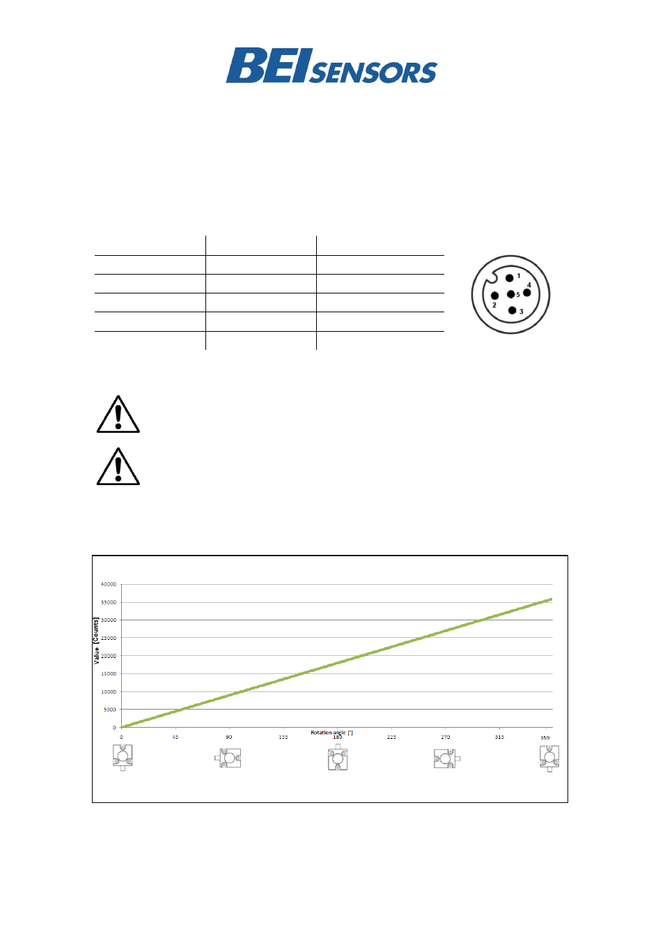
Pin Assignment
The inclinometer is connected via a 5 pin M12 A-coded round connector or cable exit.
(Standard M12, Male side at sensor, Female at connector counterpart or connection cable)
Signal
5 pin M12 connector
Cable Exit
CAN Ground
1
Green
V
S
Supply Voltage
2
Red
0 V Supply Voltage
3
Yellow
CAN High
4
White
CAN Low
5
Brown
For more detailed information about setup, measurement axes and
programming, refer CANopen Manual.
Please read the instruction leaflet carefully prior to installation.
DeviceNet Output
INC 360
– X axis Output Values (Factory Setting Resolution = 0.01)