BEI Sensors Industrial Duty Inclinometers User Manual
Page 5
Page 5
SSI Industrial Datasheet
Version 20130723
INDUST RIAL I NCLI NOMET ER 3 60°
SYNCHRONOUS S E RIAL INT E RFA CE ( S S I)
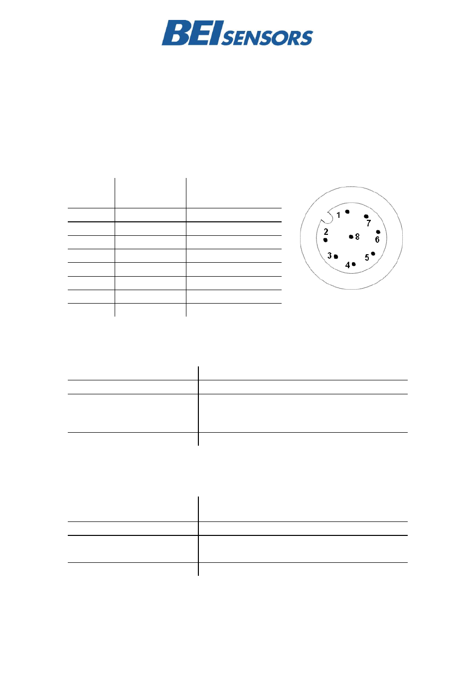
Electrical Connection
The inclinometer is connected via an 8 pin M12 A-coded round connector (male side at sensor), or a
cable.
Pin
(Connector)
Color
(Cable)
Function
1
White
GND
2
Brown
Supply Voltage
3
Green
SSI Clk+
4
Yellow
SSI Clk-
5
Grey
SSI Data+
6
Pink
SSI Data-
7
Blue
Preset
8
Red
Counting Direction
(Complement)
Preset Function
Voltage Level
Function
0 (Input = N.C. or GND)
Inactive
1 (Input
4.5V / Input
Supply
Voltage)
Preset is activated
1
. The inclinometer value will be set to 0 in
the moment the Preset Level will change to inactive again
(falling edge)
Input Resistance
110 kOhm
1) The Preset needs to be activated for at least 1s before the falling edge will be detected.
Counting Direction / Complement Function
Voltage Level
Inclinometer counting direction for clockwise rotation
(Cap Facing Towards Viewer)
0 (Input = N.C. or GND)
Down
1 (Input
4.5V / Input
Supply
Voltage)
Up
Input Resistance
110 kOhm
The inclinometer value is inverted after the Complement level is activated