AAON V3-E User Manual
Page 13
13
Mounting & Suspension
Floor Mounted
Make sure the unit is level, and mounted on a field-
supplied platform with a minimum height of 6” to allow
for proper fall on the condensate line. Other installation
provisions may be necessary according to job
specifications. V2 air handlers are designed for upflow
applications only.
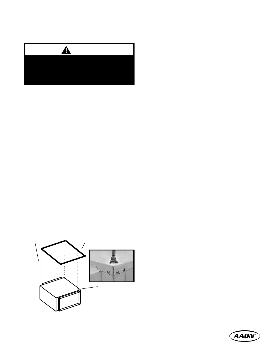
Suspended
The H2 horizontal air handler is equipped for
suspended installations. The air handler should be
lifted into position by supporting the unit with the skid
used for shipping. Suspend the air handler from its
four corners with field supplied 3/8”-16 NC “all-thread”
rods. Screw the rods into the threaded steel retainer
wells built into the air handler top and secure with nuts.
The air handler must be installed level and care should
be taken to prevent damage to the cabinet. Other
installation provisions may be necessary according to
job specifications.
Figure 13a, Suspended Horizontal Air Handler
Sealing
It is very important to keep outside air from infiltrating
the unit cabinet. Seal all piping penetrations with
Armaflex, Permagum, or other suitable sealant. Also
seal around drain connections, electrical connections,
and all other inlets where air may enter the cabinet.
This is especially important when the unit is installed in
an unconditioned area.
Cooling Equipment
Air Handler Equipped with Refrigerant Coil (DX)
This section is not intended to provide all the
information required by the designer or installer of the
refrigerant piping between the condensing units and
the air handler. The appropriate sections of the
ASHRAE Guide and the ASME standards should be
used for final information. Acceptable system design
and installation will include consideration as follows:
− Piping from the condensing unit to the indoor air
handler is the responsibility of the installing
contractor.
− Only clean “ACR” tubing should be used.
− Piping should conform to generally accepted
practices and codes.
− Care must be taken not to cross the circuits on
multiple circuit systems.
− Once piped, the interconnecting piping and air
handler MUST BE evacuated to 50 microns or
less; leak checked and charged with refrigerant as
indicated on the unit name plate.
− Make sure air handler thermal expansion valve
bulb is mounted with good thermal contact on the
correct suction line on a horizontal section, close
to the evaporator in the 4 or 8 o’clock position and
well insulated. Care must be taken to ensure the
bulb is mounted on the correct suction line on
multiple circuit systems.
− The suction line (and hot gas bypass line if
present) should be insulated for its entire length
Lines should be fastened and supported according to
local codes.
Air Handler Equipped with Chilled Water Coil
Water supply lines must be insulated with closed cell
type pipe insulation or insulation that includes a vapor
barrier. Lines should be properly fastened, drained
and supported according to local code requirements.
Field Supplied
All-thread Rod
Ceiling
Support
Structure
Wells for
Threaded Rod –
All Corners
An auxiliary (emergency) drain pan is
recommended for all applications where there is a
risk of water damage to surrounding structure or
furnishings. Refer to local codes.
NOTE