Assembly and installation – CHIEF PACCC2 User Manual
Page 5
Installation Instructions
PACCC2
5
Assembly and Installation
Accessory Assembly - PACCC2 Alone
The PACCC2 is designed to accommodate both 200 x 200
VESA and 14" x 14" display mounting patterns. If 200 x 200
pattern is required use the inner mounting holes when
connecting height-adjust brackets (B) to center plate (D). (See
Figure 1)
NOTE:
The 14" x 14" display mounting pattern is NOT identical
to a 400 x 400 VESA display mounting pattern.
IMPORTANT ! :
If installing the PACCC2 with the PACLR2,
proceed to the Assembly using PACLR2 section.
1.
Connect center plate (D) to height-adjust brackets (B) by
installing four #10-24 x 1/2" button head cap screws (G)
through holes on center plate (D) and height-adjust
brackets (B). (See Figure 1)
2.
Secure center plate (D) to height-adjust uprights (B) by
installing two #10-24 x 1/2" button head cap screws (G)
through back holes on center plate (D) and height-adjust
brackets (B). (See Figure 1)
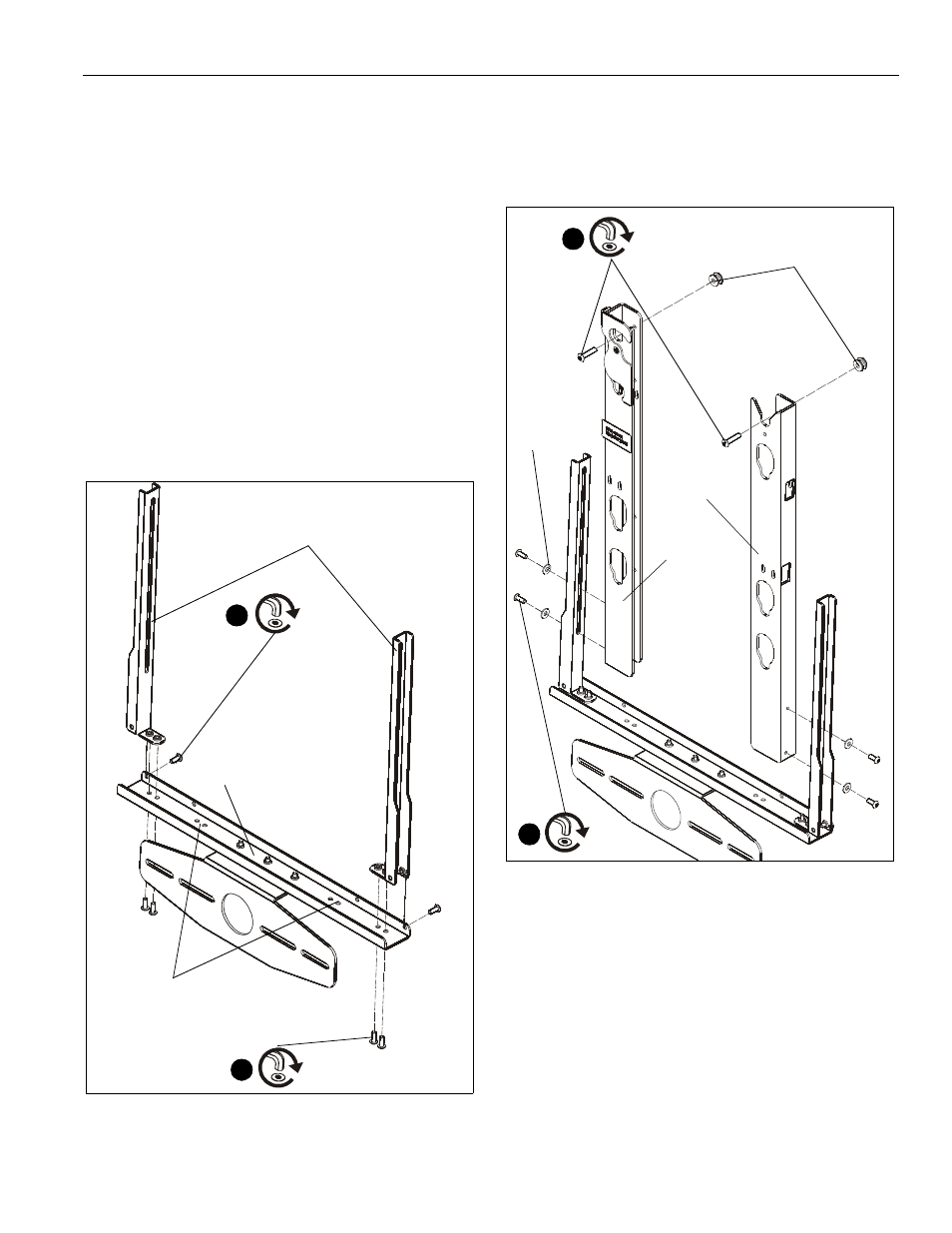
Figure 1
3.
Install two mounting buttons (E) to uprights (A and C) using
four #10-24 x 7/8" button head cap screws (H). (See Figure 2)
4.
Connect left and right uprights (A and C) to height adjust
brackets (B) using four #10-24 x 1/2" button head cap
screws (G) and four #10 washers (J). (See Figure 2)
Figure 2
Assembly Using PACLR2
IMPORTANT ! :
When installing the PACCC2 to the PACLR2,
the uprights shipped with the PACCC2 will NOT be used as the
uprights already installed on the PACLR2 are identical.
1.
Connect center plate (D) to height-adjust brackets (B) by
installing four #10-24 x 1/2" button head cap screws (G)
through outer holes on center plate (D) and height-adjust
brackets (B). (See Figure 1)
2
(B) x 2
(D)
(G) x 2
1
(G) x 4
holes to use for
200 x 200 VESA mounting
(E) x 2
(H) x 2
3
(G) x 4
4
(J) x 4
(A)
(C)