Setup and installation – CHIEF PACLR1 User Manual
Page 4
PACLR1
Installation Instructions
4
Setup and Installation
If the PACCC1 Center Channel Speaker accessory is being
installed, install PACCC1 components to PACLR1 following the
instructions provided with the PACCC1 before continuing.
Configure Accessory for Display
Determine VESA Mounting Pattern
The PACLR1 is designed to accommodate both a 200 x 200
VESA and a 14" x 14" display mounting pattern. The accessory
is shipped from the factory configured for the 14" x 14" pattern
and will need to be reconfigured if the 200 x 200 pattern is
required. (See Figure 2)
NOTE:
The 14" x 14" display mounting pattern is NOT identical
to a 400 x 400 VESA display mounting pattern.
WARNING:
IMPROPER INSTALLATION CAN LEAD TO
ACCESSORY AND/OR DISPLAY FALLING CAUSING
SEVERE PERSONAL INJURY OR DAMAGE TO
EQUIPMENT! If the display being installed does not have a
VESA 200 x 200 or 14" x 14" mounting pattern an interface
bracket will be required to install this accessory. Consult a
Chief Customer Service representative by calling
800.582.6480 or by visi
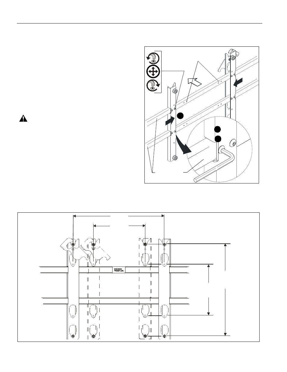
To reconfigure to the 200 x 200 VESA pattern;
1.
Remove eight button head cap screws securing uprights to
speaker rails. (See Figure 1)
2.
Reposition uprights so that eight mounting holes are aligned
with eight inner (200 x 200) mounting holes in speaker rails.
(See Figure 1)
3.
Secure uprights to speaker rails using eight button head cap
screws. (See Figure 1)
Figure 1
Speaker Rails
2
x8
3
1
200 x 200
Figure 2
200 x 200
200 x 200
14" x 14"
14" x 14"