CHIEF FCA103 User Manual
Page 6
FCA103
Installation Instructions
6
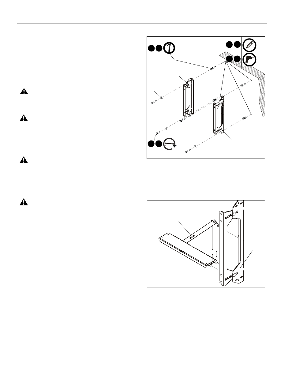
Installing to a Concrete Wall
1.
Determine the center of the TV screen, and where it should
be located on the wall.
2.
Line up the notches on bracket (A and B) with center of
screen marking to determine vertical center. (See Figure 1)
3.
Measure up 8 3/4" (222.2mm) from the center point to mark
location of the upper mounting slots. (See Figure 1)
4.
Using a level, mark the wall through both upper mounting
slots. (See Figure 3)
CAUTION:
MINIMUM HORIZONTAL DISTANCE
BETWEEN WALL BRACKETS IS 16" (406.4mm). Do not
place mounting brackets closer together than 16" (406.4mm).
WARNING:
INSTALLING THE FCA103 INTO
UNDERRATED OR DAMAGED CONCRETE CAN LEAD TO
SERIOUS INJURY OR DAMAGE TO PRODUCT! When
installing into concrete, only install the FCA103 into concrete
at least 8" in depth or into 8"x8"x16" concrete blocks! Never
install the FCA103 into cracked, chipped or flaking concrete.
WARNING:
ELECTRICAL SHOCK HAZARD! CUTTING
OR DRILLING INTO ELECTRICAL CORDS OR CABLES
CAN CAUSE DEATH OR SERIOUS PERSONAL INJURY!
ALWAYS make certain area behind mounting surface is free
of electrical wires and cables before drilling or installing
fasteners.
WARNING:
EXPLOSION AND FIRE HAZARD! CUTTING
OR DRILLING INTO GAS PLUMBING CAN CAUSE DEATH
OR SERIOUS PERSONAL INJURY! ALWAYS make certain
area behind mounting surface is free of gas, water, waste, or
any other plumbing before cutting, drilling, or installing
fasteners.
5.
Drill one 5/16" (7.9mm) pilot hole at each marking.
6.
Install an anchor into each pilot hole using a hammer,
making sure that the anchor is flush with the wall.
NOTE:
If desired CPU location is off to the side of the display,
reverse brackets (A and B) from how they are shown in
Figure 3.
NOTE:
Either Fischer UX10 anchors or the concrete anchors
shipped with the Fusion mount may be used.
7.
Use two 5/16 x 2-1/2" lag bolts and two 5/16" flat washers
to attach top of brackets (A and B) to anchors in wall.
8.
Mark the attachment points for the lower mounting slots.
(See Figure 3)
9.
Drill one pilot hole at each marking for lower mounting
holes. (See Figure 3)
10. Install an anchor into each pilot hole using a hammer.
11. Use two 5/16 x 2-1/2" lag bolts and two 5/16" flat washers
to attach the brackets to the wall through the lower
mounting holes. (See Figure 3)
Figure 3
Installing Shelf to Brackets
1.
Hang shelf bracket (C) onto right wall bracket (B). (See
Figure 4)
Figure 4
2.
Use #10-24 x 5/8" carriage bolt (E), #10-24 wing nut (L),
1/4" washer (F) and #10 washer (H) to secure locking tab
(K) to right wall bracket (B). (See Figure 5)
8
5
6
4
9
x4
anchors x 4
10
7 11
x 4
x 4
(A)*
(B)*
*reverse brackets to install CPU shelf to the outside
(C)
(B)