Installation – CHIEF FCA103 User Manual
Page 5
Installation Instructions
FCA103
5
INSTALLATION
Locate Mounting Site
WARNING:
Exceeding the weight capacity can result in
serious personal injury or damage to equipment! It is the
installer’s responsibility to make sure the combined weight of
all components atttached to the FCA103 does not exceed
250 lbs (113.4 kg) or the maximum weight limit of the specific
Fusion mount being attached. The maximum weight that can
be installed onto the FCA103 shelf is 30 lbs (13.6 kg).
The FCA103 can be installed to either wood studs or a concrete
wall. The minimum distance between fasteners must be 16"
whether installing to 2" x 4" wood studs or concrete.
NOTE:
Proceed to either the Installing to a Wood Stud Wall
section or the Installing to a Concrete Wall section.
NOTE:
If already installed, Fusion mount must be uninstalled
prior to FCA103 installation. Set aside wall mounting
hardware as it will be used again for FCA103 mounting.
Installing to a Wood Stud Wall
1.
Determine the center of the TV screen, and where it should
be located on the wall.
2.
Locate the closest 2" x 4" stud to the left and right of the
selected location.
NOTE:
If the screen area lies over a stud, use that stud and the
stud to either the left or right of it.
3.
Line up the notches on mount (A) with center of screen
marking to determine vertical center. (See Figure 1)
4.
Measure up 8 3/4" (222.2 mm) from the center point to mark
location of the upper mounting slots.
Figure 1
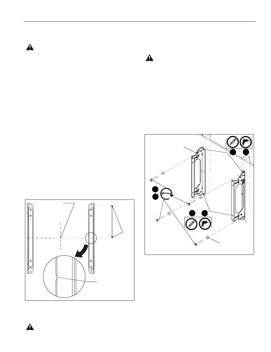
5.
Using a level, mark the wall on each stud to attach the
brackets through the upper mounting slots. (See Figure 2)
WARNING:
ELECTRICAL SHOCK HAZARD! CUTTING
OR DRILLING INTO ELECTRICAL CORDS OR CABLES
CAN CAUSE DEATH OR SERIOUS PERSONAL INJURY!
ALWAYS make certain area behind mounting surface is free
of electrical wires and cables before drilling or installing
fasteners.
WARNING:
EXPLOSION AND FIRE HAZARD! CUTTING
OR DRILLING INTO GAS PLUMBING CAN CAUSE DEATH
OR SERIOUS PERSONAL INJURY! ALWAYS make certain
area behind mounting surface is free of gas, water, waste, or
any other plumbing before cutting, drilling, or installing
fasteners.
6.
Drill one 7/32" (5.5mm) pilot hole in each stud.
7.
Use two 5/16 x 2-1/2" lag bolts and two 5/16" flat washers
to attach top of brackets (A and B) to wall. (See Figure 2)
NOTE:
If desired CPU location is off to the side of the display,
reverse brackets (A and B) from how they are shown in
Figure 2.
Figure 2
8.
Mark the attachment points for the lower mounting slots,
making sure the attachment points are located on the studs.
(See Figure 2)
9.
Drill 7/32" (5.5mm) pilot holes at markings for lower
mounting holes. (See Figure 2)
10. Use two 5/16 x 2-1/2" lag bolts and two 5/16" flat washers
to attach the mount to the wall through the lower mounting
holes. (See Figure 2)
11. Proceed to Installing Shelf to Brackets Section.
Center of screen
8-3/4"
Vertical center
of mount
(222.2mm)
8
9
5
6
x 4
7
10
x 4
(A)*
(B)*
*reverse brackets to install CPU shelf to the outside