CHIEF KSA1019 User Manual
Page 7
Installation Instructions
KSA1019
7
Swing Arm Recessed Display Installation
1.
Carefully place display face down on a clean and dry
surface.
2.
Determine depth of recessed mounting holes relative to
back surface of display.
3.
Select proper length spacer and screw from table below:
IMPORTANT ! : All spacers used should be the same
length. If the recess depths result in multiple spacer
lengths, then select the longer spacer.
4.
Place the four (F or G) spacers over each mounting hole on
the back of display. (See Figure 5)
5.
Orient mount so that mounting holes in the Centris Turntite
head are aligned with the holes in the spacers (F or G).
Rotate the Centris Turntite head as required (See Figure 5).
CAUTION:
IMPROPER INSTALLATION CAN LEAD TO
DISPLAY FALLING CAUSING SERIOUS PERSONAL
INJURY OR DAMAGE TO EQUIPMENT! Using screws of
improper size may damage your display! Proper screws will
easily and completely thread into display mounting holes.
6.
Using Phillips screwdriver, install four Phillips screws
(C or D) through the mounting holes in Centris Turntite head
and the spacers (F or G), into display. (See Figure 5)
7.
Tighten all four screws. Do not overtighten!
8.
Return to mount installation section to continue.
Figure 5
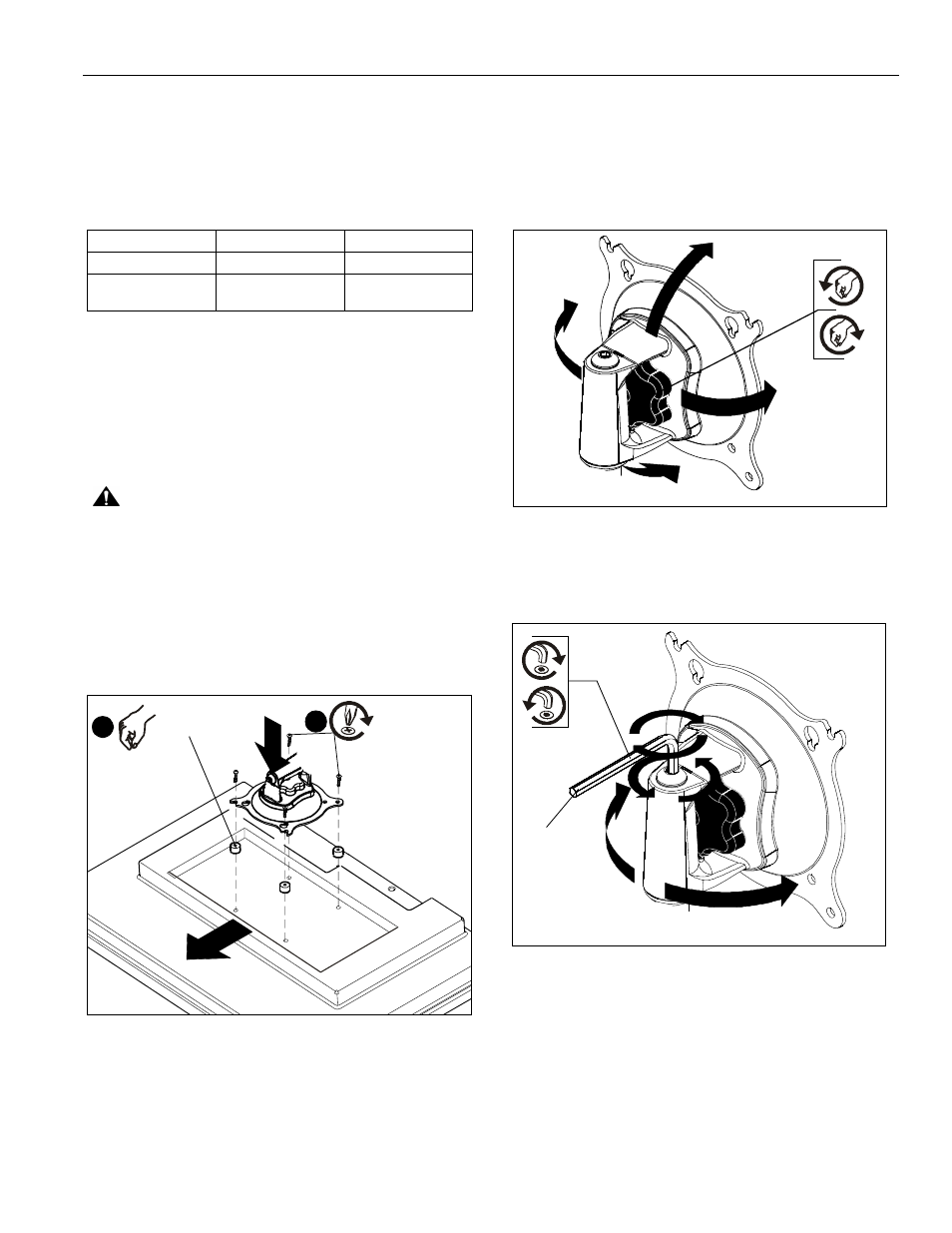
Adjustments
The KSA1019 provides for Pitch, Roll, Yaw and display pivot
tension adjustment.
To adjust display Pitch/Roll/ Yaw tension:
1.
Turn adjustment knob, located on back of Centris Turntite
head, clockwise to increase tension or counter-clockwise to
decrease. (See Figure 6)
Figure 6
To adjust display pivot tension:
1.
Using hex wrench provided (G), turn adjustment screw
clockwise to increase tension or counter-clockwise to
decrease tension. (See Figure 7)
Figure 7
IF recess DEPTH is: THEN use spacer:
AND screw:
3/8" or less
F (3/8" long)
C (M4 x 20mm)
More than 3/8" up to
and including 3/4"
G (3/4" long)
D (M4 x 30mm)
(
TOP
(F) or (G) x 4
6
4
(C) or (D) x 4
(G)