Assembly and installation, Array installation (k1p22h only), Display installation – CHIEF K1P Series User Manual
Page 7
Installation Instructions
K1P Series
7
Assembly And Installation
Connecting to Pole
1.
Determine approximate location for mount keeping in mind
display size, extension, height adjustment requirements.
2.
Place mount (A) against pole with clamp (E) on opposite
side of pole. (See Figure 1)
Figure 1
3.
Using 5/32” hex key (L) and appropriate length screws,
loosely attach assembly to pole clamp (E). If installing to
1 1/2” NPT pipe, use 1/4-20 x 1 1/2” button head cap screws
(F). If installing to 1 1/2” diameter pipe, use 1/4-20 x 1"
button head cap screws (G). (See Figure 1)
4.
Position mount at desired height and orientation.
5.
Equally tighten screws against mount and the pole clamp.
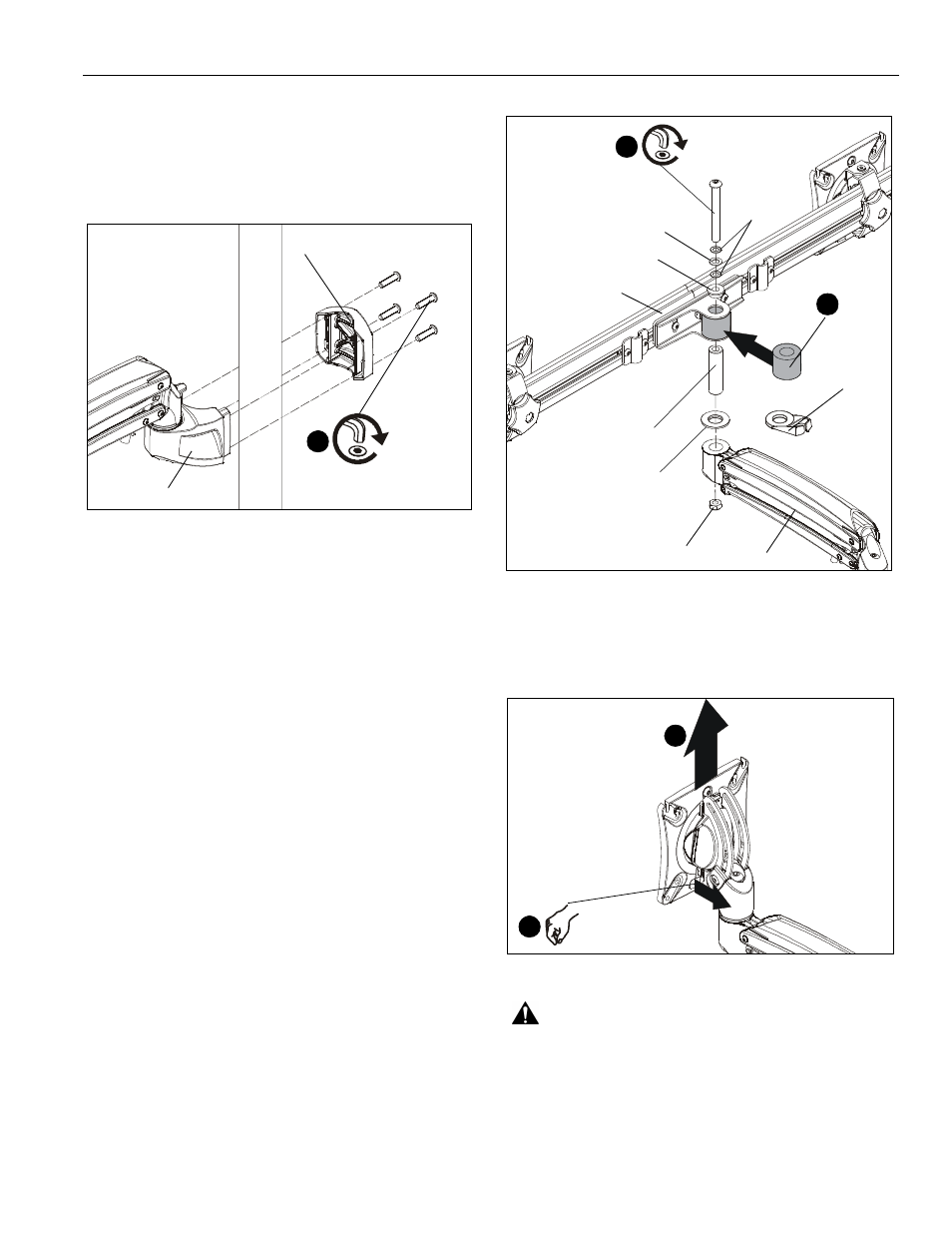
Array Installation (K1P22H ONLY)
1.
Slide rotational spacer (J10) into opening on array
attachment bracket. (See Figure 2)
2.
Use 5/16-18 x 3" button head cap screw (J3), two thin steel
washers (J8), plastic spacer (J9), pocket washer (J5), pivot
pin (J4), pivot point spacer (J12) and 5/16-18 lock nut (J6)
to secure array (J1) to K1 arm (A). (See Figure 2)
NOTE:
Cable clip (J11) can be used in place of pivot point
spacer (J12) if additional cable management is desired.
(See Figure 2)
Figure 2
Display Installation
1.
Remove quick release faceplate from mount by pulling
quick release lever and sliding faceplate off mount. (See
Figure 3)
Figure 3
WARNING:
Only remove display from mount when the
display can be lifted up from the mount! DO NOT remove
display unless the display is in the upright position! See
Display Removal section for details.
3
(F or G) x 4
(E)
(A)
(J10)
1
(J3)
2
(J9)
(J8) x 2
(J5)
(J1)
(J4)
(J6)
(A)
(J12)
(J11)
or
quick release lever
1
1