Cable management – CHIEF F-Series User Manual
Page 13
Installation Instructions
Model: F-Series
13
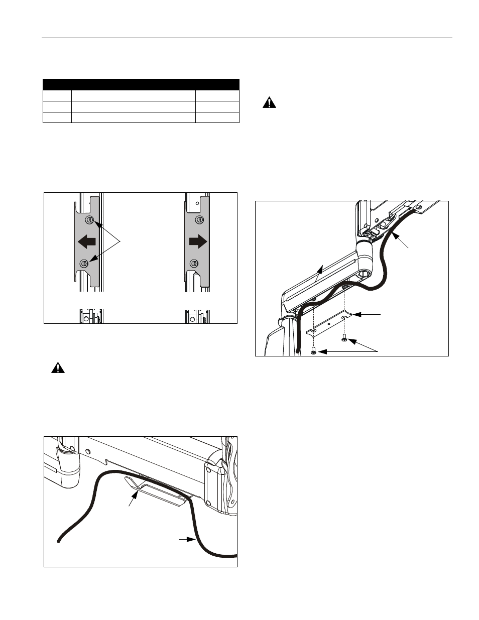
CABLE MANAGEMENT
1.
Attach all cables to display.
2.
Open the cable management bracket by sliding it
towards the edge of the arm (See Figure 20).
NOTE: If necessary, cable management bracket attach
screws may be loosened using hex key (30).
Figure 20: Height Adjustable Arm -
Cable Management Bracket
CAUTION: Ensure that adequate cable slack exists for
movement of display, and that cables will not be
pinched when bracket is closed.
3.
Carefully insert cables into bracket (See Figure 21).
Figure 21: Height Adjustable Arm - Cable Path
4.
Close cable management bracket by sliding it back
towards the centerline of the arm (See Figure 20).
NOTE: If necessary, cable management bracket attach
screws may be tightened using hex key (30).
CAUTION: Ensure that adequate cable slack exists for
movement of display, and that cables will not be
pinched by installation of cover (10) or screws (20).
5.
Carefully insert cables in cavity located in lower
portion of mount arm (See Figure 22).
6.
Using Phillips screwdriver, install cover (10) with two
screws (20).
Figure 22: Static Arm - Cable Path
NOTE: Installation is complete.
Item
Description
Qty
10
COVER, Arm
1 per arm
20
SCREW, Phillips Flat Machine, 8-32 x 3/8"
2 per arm
30
WRENCH, Hex, 3/32" (provided)
1
OPEN Position
CLOSED Position
View from Bottom
Attach
Screws
Cable Path (typical)
NOTE: Display not shown for clarity.
Cable Management
Bracket (in open position)
90
20
Cable Path
(typical)
10