CHIEF F-Series User Manual
Page 12
Model: F-Series
Installation Instructions
12
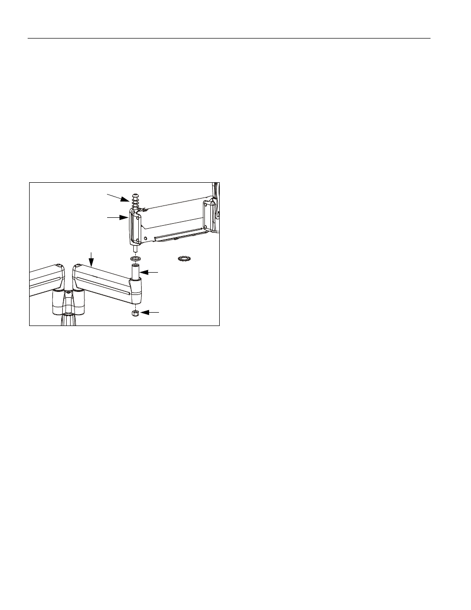
MODIFICATION
If desired, each arm assembly (10) may be modified to
prevent movement of the outer arm relative to the inner
arm (without loosening the adjustment screw).
NOTE: Spacer (shipped configuration) will allow limited
movement of outer arm relative to inner arm,
dependent upon tension of screw. Washer (80)
will lock arms together. See "ADJUSTMENT" for
detail.
1.
Using 3/16" hex key, loosen screw until nut can be
removed (See Figure 19). Retain nut. Screw and
washers may remain in outer arm.
Figure 19: Multi-Dual Arm Modification
2.
Lift outer arm from pin (with screw and washers) and
place on protective surface.
3.
Remove spacer from pin (See Figure 19).
4.
Install washer (80) on pin (See Figure 19).
5.
Re-install outer arm (with screw and washers) on pin
(See Figure 19).
6.
Insert and hold nut in lower bore of inner arm (See
Figure 19).
7.
Tighten screw as required using 3/16" hex key (See
Figure 19).
8.
Proceed to "CABLE MANAGEMENT" (for display with
RECESSED mounting holes), or to "DISPLAY
INSTALLATION" (for all other display configurations).
spacer or
80
nut
Outer arm
pin
Screw & washers
Inner arm