CHIEF PCS Series User Manual
Page 6
PCS Series
Installation Instructions
6
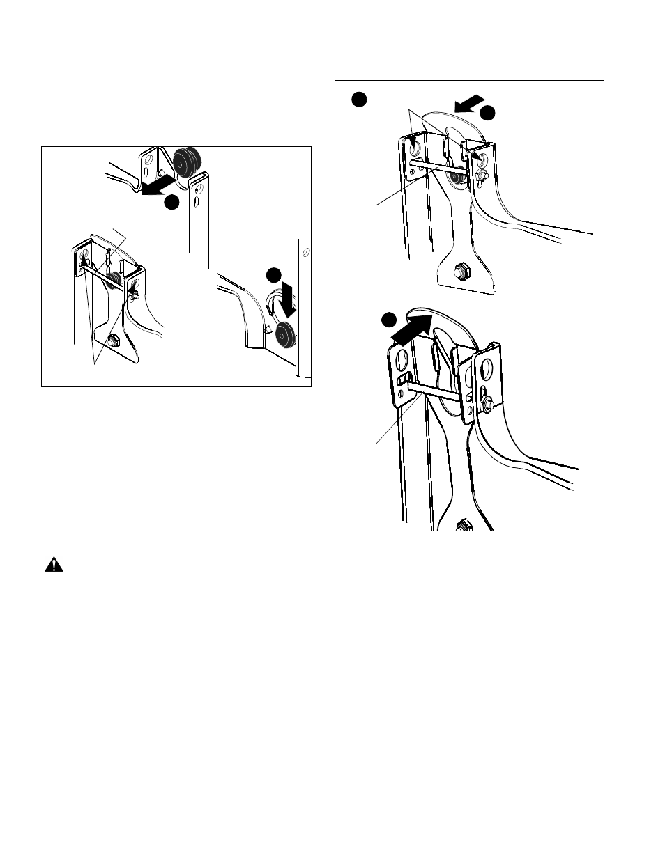
NOTE:
Holes are provided in the faceplate for use with a
padlock or similar locking device, if desired. In addition,
the pin and nut may be removed from the upper holes
and moved to the lower holes for use as a more
permanent locking device. (See Figure 4).
Figure 4
Removing Display
1.
Disconnect all power/audio/video cables.
2.
Remove bolt or padlock from faceplate (if used).
(See Figure 5)
NOTE:
The pin may have been used as a more permanent
locking device. If so, remove nut and pin and move
from the lower holes to the upper holes.
3.
Pull back on flag on upper mounting hole and press pin
down into "Open" position. (See Figure 5)
WARNING:
THE DISPLAY MAY WEIGH IN EXCESS OF
40 LBS EACH! Always use two people and proper lifting
techniques when installing or positioning display.
4.
Carefully lift display from PCS.
5.
Lift up on pin and place flag back against faceplate to return
it to "Closed" position. (See Figure 5)
Figure 5
4
5
To use as a more
permanent lock, remove
pin and nuts and move
to lower holes.
A padlock or bolt may
be placed through latch holes
3
2
5
Remove bolt
or padlock
if used
Pin in
"Closed"
position -
Move to
"Open"
position to
remove
display
Pin in
"Open"
position -
Move to
"Closed"
position
after display
is removed