Installation – CHIEF PDC Series User Manual
Page 5
Installation Instructions
PDC Series
5
INSTALLATION
WARNING:
FAILURE TO PROVIDE ADEQUATE
STRUCTURAL STRENGTH FOR THIS COMPONENT CAN
RESULT IN SERIOUS PERSONAL INJURY OR DAMAGE
TO EQUIPMENT! It is the installer’s responsibility to make
sure the structure to which this component is attached can
support five times the combined weight of all equipment.
Reinforce the structure as required before installing the
component.
Attaching PDC to Extension Column
CAUTION:
Watch for pinch points. Do not place fingers
between movable parts.
IMPORTANT ! : These installation instructions assume
that a 1-1/2" NPT or NPSM (Schedule 40, 0.154"
minimum thickness steel or aluminum - ASTM B221)
extension column (not included) has been properly
installed and is in place.
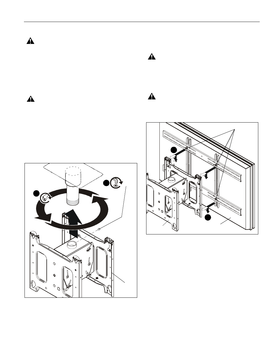
1.
Thread the PCD mount (A) onto the existing 1-1/2" NPT or
NPSM extension column (not included) until tight, with a
minimum of four threads engaged. (See Figure 1)
Figure 1
2.
Install and tighten the 5/16-18 x 3/8" set screw (C). (See
Figure )
Attaching Interface Bracket to Displays
1.
Attach PSBU interface brackets to displays following
instructions included with interface brackets.
Installing Displays on PDC
WARNING:
EXCEEDING MAXIMUM WEIGHT CAPACITY
CAN LEAD TO SERIOUS PERSONAL INJURY OR
DAMAGE TO EQUIPMENT! It is the installers responsibility
to ensure the total amount of weight placed on the mount
does not exceed 400 lbs (181.44 kg) [200 lbs (90.72 kg) each
faceplate].
WARNING:
DISPLAY MAY WEIGH IN EXCESS OF
40 LBS (18.14 KG)! Always use two people and proper lifting
techniques when installing or positioning display.
Figure 2
1.
While supporting each side of display, align four mounting
buttons on interface bracket with four mounting holes on
PDC. (See Figure 2) and (See Figure 3)
1
2
(C) x 1
(A)
(A)
Display
1
2
Mounting
button