Installing display – CHIEF TS525TU User Manual
Page 11
TS525TU
Installation Instructions
11
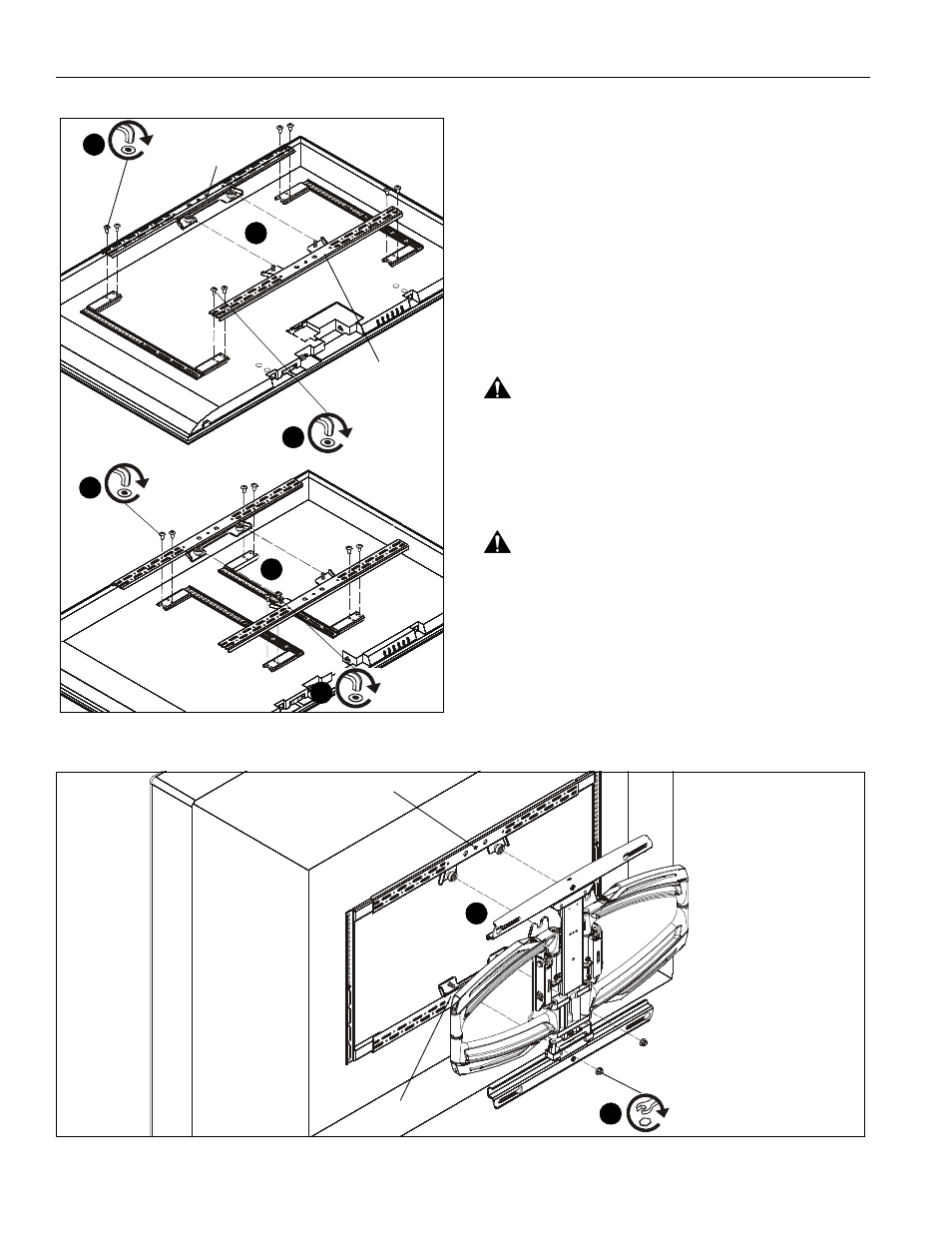
Figure 14
8.
Connect top interface support (R) to uprights (P and Q)
using four #10-24 x 1/2" button head cap screws (W). (See
Figure 14)
NOTE:
If possible install screws diagonally across from each
other in order to provide maximum support in Steps 8
and 9.
9.
Connect bottom interface support (S) to uprights (P and Q)
using four #10-24 x 1/2" button head cap screws (W). (See
Figure 14)
10. When connecting bottom interface support (S) to uprights,
make sure that it is aligned vertically with top interface
support (R). (See Figure 14)
Installing Display
Using Interface Bracket
WARNING:
Exceeding the weight capacity can result in
serious personal injury or damage to equipment! It is the
installer’s responsibility to make sure the combined weight of
all components attached does not exceed 125 lbs (56.7 kg).
Use with products heavier than the maximum weight
indicated may result in collapse of the mount and its
accessories causing possible injury.
WARNING:
Display may be very heavy! Ensure display
can be safely lifted and maneuvered as required to install on
wall plate. Failure to take adequate precautions can result in
serious personal injury or damage to equipment!
1.
Hang interface bracket and display to faceplate by placing
two mounting buttons on top interface support (R) over two
teardrop grooves on top of faceplate. (See Figure 15)
2.
Secure interface bracket and display to faceplate by
installing two 5/16-18" flange nuts (X) onto screws on lower
interface support (S). (See Figure 15)
(W) x 4
8
(R)
(S)
(W) x 4
9
10
10
(W) x 4
8
(W) x 4
9
narrow mounting hole pattern
Figure 15
1
2
(X) x 2
(R)
(S)