Adjustments – CHIEF JWDIW Series User Manual
Page 6
JWDIW Series
Installation Instructions
6
Optional Trim Installation
1.
Remove paper covering adhesive from tape squares (L)
and affix three tape squares to inside lower flange of each
trim piece (B). (See Figure 7)
2.
Orient trim pieces (B). (See Figure 7)
3.
Remove paper covering adhesive back from tape squares
(L) on trim and press trim (B) against inner wall of box.
(See Figure 7)
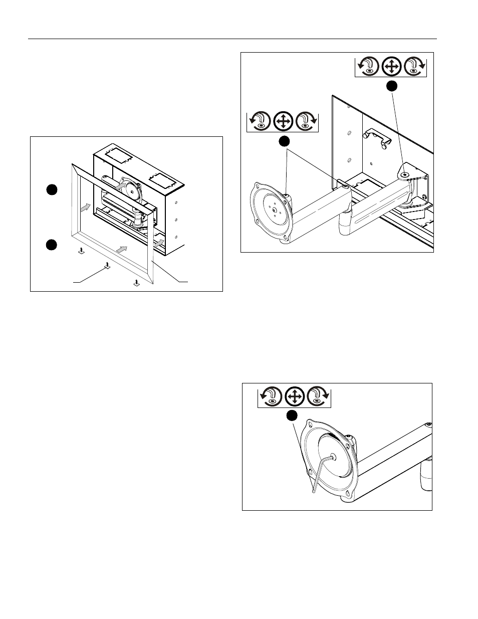
Figure 7
ADJUSTMENTS
PIVOT / SWING ARM Tension
1.
Using 3/16" hex key (P), slightly loosen or tighten the pivot/
swing tension adjustment screw(s) as necessary (See
Figure 8).
2.
Using 7/32" hex key (Q), slightly loosen or tighten the
adjustment screw at end of swing arm. (See Figure 8)
Figure 8
DISPLAY ROLL, PITCH, YAW Tension
1.
Disconnect all wires and cable from the display.
2.
Remove two Lower screws securing display to Centris cup.
3.
Loosen two Upper screws securing display.
4.
Lift display upward and away from mount.
5.
Using 3/16" hex key (P), turn the tension adjustment screw
clockwise to increase tension, or counter-clockwise to
decrease tension. (See Figure 9)
6.
Re-install display.
Figure 9
(L) x 12
2
(B) x 4
3
1
2
5