CHIEF JWDIW Series User Manual
Page 5
Installation Instructions
JWDIW Series
5
Display Installation
NOTE:
If the display being installed has a 100x100 VESA
mounting pattern, no interface bracket is required and
the display can be mounted directly to the Centris cup
as outlined below.
NOTE:
If the display being installed requires an interface
bracket, refer to the interface bracket installation
instructions.
WARNING:
IMPROPER INSTALLATION CAN LEAD TO
DISPLAY FALLING CAUSING SERIOUS PERSONAL
INJURY OR DAMAGE TO EQUIPMENT! Using screws of
improper size may damage your display! Proper screws will
easily and completely thread into display mounting holes.
Ensure that screws are not too long.
WARNING:
IMPROPER INSTALLATION CAN LEAD TO
DISPLAY FALLING CAUSING SERIOUS PERSONAL
INJURY OR DAMAGE TO EQUIPMENT! Inadequate thread
engagement in display may cause display to fall! Back out
screws ONLY as necessary to allow installation of Centris
cup!
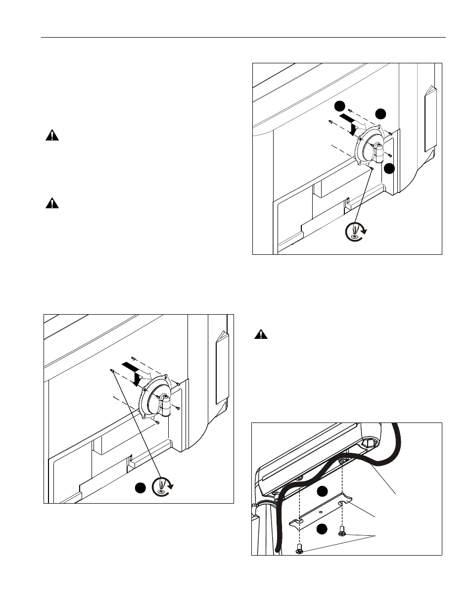
1.
Start two M4 x 8mm Phillips pan head screws (included in
hardware kit) into upper mounting holes in display back.
(See Figure 4)
NOTE:
Leave at least 1/8" of each screw protruding out back
of display.
Figure 4
2.
Align two screws in display back with upper mounting holes
in Centris cup and lower display until screws are seated in
lower area of teardrop mounting holes. (See Figure 5)
3.
Install two more of the same screws through lower mounting
holes in Centris cup and into display back. (See Figure 5)
4.
Tighten all hardware.
5.
Route cables and wires to display.
Figure 5
Cable Management
1.
Attach all cables to display.
2.
If necessary, use cable tie mounts (M) and cable ties (R) to
secure cables within MAC501.
CAUTION:
Ensure that adequate cable slack exists for
movement of display, and that cables will not be pinched by
installation of cover (H) or screws (J).
3.
Carefully insert cables in cavity located in lower portion of
mount arm (See Figure 6).
4.
Using Phillips screwdriver, install cover (H) with two screws
(J). (See Figure 6)
Figure 6
x2
1
x 2
2
3
4
(J) x 4
Cable Path
(typical)
(H) x 2
3
2