CHIEF TPS Series User Manual
Page 8
TPS Series
Installation Instructions
8
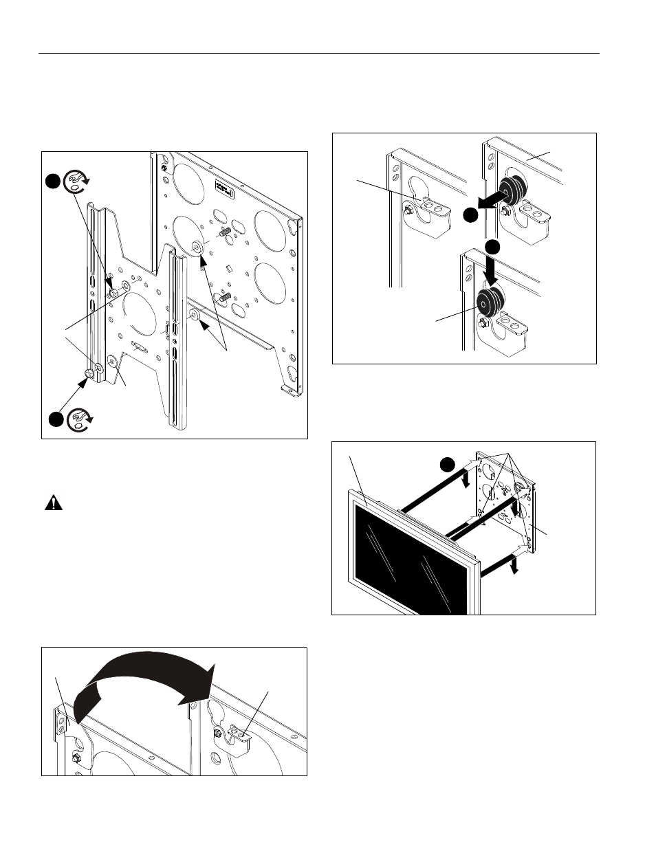
3.
Secure top of faceplate (A) to the truss plate (B) using one
3/8" flat washer (E) and one 3/8" Stover lock nut (C). (See
Figure 8)
4.
Secure bottom of TPS faceplate (A) to the truss plate (B)
using one .094" washer (F), one 3/8" flat washer (E) and
one 3/8" Stover lock nut (C). (See Figure 8)
Figure 8
DISPLAY INSTALLATION
WARNING: Exceeding the weight capacity can result
in serious personal injury or damage to equipment! It is
the installer’s responsibility to make sure the combined
weight of all components attached to the TPS does not
exceed 150 lbs (68.04 kg).
IMPORTANT ! : Make sure no power is supplied to the
display and the latching flag on the TPS is in the
unlocked position before attempting to attach the display.
(See Figure 9)
Figure 9
1.
Attach interface bracket (G) to display using the instructions
included with the interface bracket kit.
2.
Lift and maneuver display such that all mounting buttons fit
into mounting slots on TPS faceplate (A). (See Figure 10)
Figure 10
3.
Lower display firmly into place. Ensure each button has fully
seated in its mounting slot. (See Figure 10) and (See
Figure 11)
Figure 11
Horizontal
3
Installation
(C)
(D) x 2
(F) x 1
(E) x 2
4
(C)
Unlocked
Locked
Mounting
2
slot
(A)
Mounting button
3
(A)
Mounting slots (x4)
Display
3
Note: Trusses not
shown for clarity.