Installation – CHIEF TPS Series User Manual
Page 6
TPS Series
Installation Instructions
6
INSTALLATION
WARNING:
Failure to provide adequate structural strength
for this component can result in serious personal injury or
damage to equipment! It is the installer’s responsibility to
make sure the structure to which this component is attached
can support five times the combined weight of all equipment.
Reinforce the structure as required before installing the
component.
The TPS assembly is designed to accommodate vertical or
horizontal truss/pole mounting. For horizontal pole mounting,
proceed to Horizontal Installation section. To use the TPS in
the vertical configuration, proceed to Vertical Installation
section.
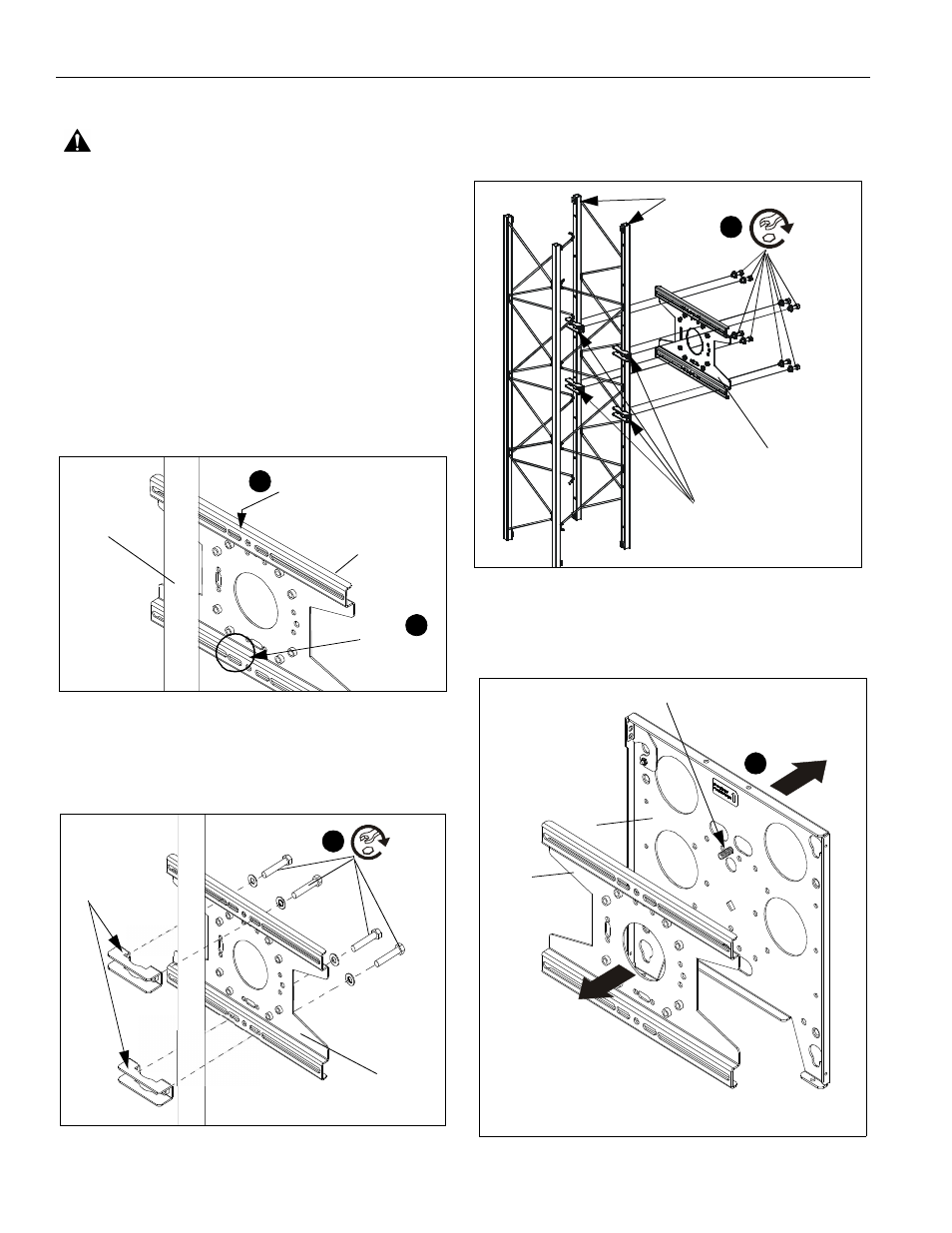
Vertical Installation
1.
Verify truss plate (B) is properly oriented for installation.
(See Figure 1)
Figure 1
2.
Securely anchor truss plate (B) to pole using Chief TPK
clamp kit (not included) following instructions and using
hardware included in kit. (See Figure 2) and (See Figure 3)
Figure 2
NOTE:
The orientation of the truss plate (B) when mounted on
a truss is the same as when mounted on a pole. The
number of clamps required will depend on the number
of trusses used for installation. (See Figure 3)
NOTE:
Figure 3
3.
Position faceplate (A) in front of truss plate ensuring the
mounting studs face the truss plate. (See Figure 4)
Figure 4
Slot at
Recessed, slotted flat
(B)
bottom
surface against pole
1
1
Vertical
pole
(B)
TPK clamp kit
(not included)
2
x 4
(B)
Trusses used (2) (example)
TPK clamps x 4
(not included)
x 8
2
To Display
Side with mounting studs towards truss plate (B)
To
Trusses
Note: Trusses/poles
not shown for clarity.
(B)
(A)
3
or poles