2 diameter gauge, 3 width sonar (option) – CEMB USA C71_2 SE evo (B) User Manual
Page 17
17
40
m
m
Use and maintenance manual Rev. 10-2011
ENGLISH
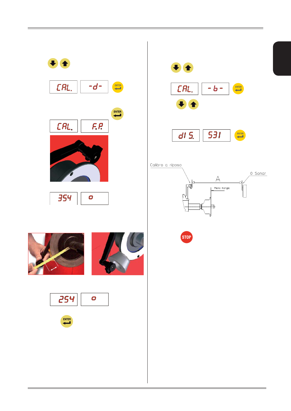
6.6.2 Diameter gauge
E
Display the SETUP menu
P
1. ress
to view the diameter
gauge CALIBRATION function.
m
Place the round part of the gauge terminal on the
flange as shown in the figure and press
Th
2.
e number 354 ± 3° appears on the left display .
Turn
3.
the gauge downward position the round part
of the gauge terminal at 40 mm (radial distance)
from the flange as indicated in the figure; alternati
vely use one of the cones provided as shown in the
images
The nu
4.
mber 254 ± 3° should appear on the left
display. The calibration is already correct.
If not, press the
button holding the gauge still at 40
mm: the number 254 appears on the left display.
Return the gauge to rest position.
6.6.3 Width sonar (option)
Display the SETUP menu
P
1. ress
to view the width sonar
CALIBRATION
function.
Set with
2.
the distance in mm betwe
en the Sonar sensor (0 sonar) and t
he end of the
distance gauge (at rest).
A = Distance: Gauge at rest to
0 sonar
In the event of incorrect input in the width gauge calibration
function, press
to cancel it.
Setup