CEMB USA C29 (A) User Manual
Page 8
5
b
I 0337 -
8
I 0337 -
9
GB
GB
5 - Instructions for use of the wheel balancer
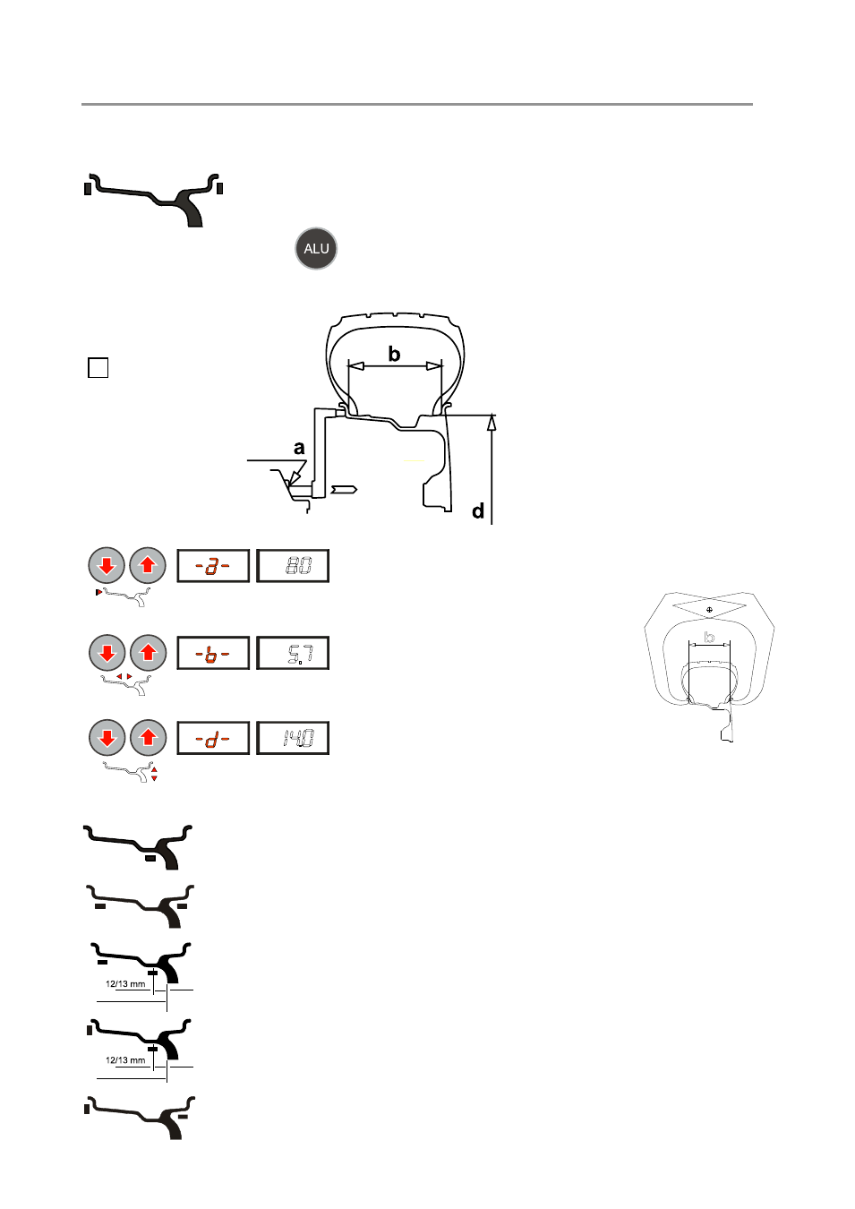
5.1 - Setting the wheel dimensions
a)
DYNAMIC balancing of steel or light alloy rims with application of clip-on
weights on the edge of the rim.
From the measurement frame, press
to select the desired correction mode.
The illuminated LEDs indicate the position where the weights should be applied. If a spin has already been carried
out, each time the mode is changed, the processor automatically recalculates the unbalance values on the basis of
the new setting.
- Set the distance “a” between the inside of the wheel
and the machine
- Set the nominal width, normally indicated on the
rim, or measure the width “b” using the caliper
gauge supplied.
- Set the nominal diameter “d” indicated on the tyre.
Reading
- Measuring
- Setting
The
STATIC mode is required for motorcycle wheels or when it is not possible to
place the counterweights on the two sides of the rim.
Balancing of light alloy rims with application of adhesive weights on the rim
shoulders.
Balancing of light alloy rims with hidden application of the other adhesive weight.
Outer weight position is fixed.
Combined application: clip-on weight inside and hidden adhesive weight on
outside (Mercedes). Outer weight position is fixed.
Combined application: adhesive weight outside and clip-on weight inside.
This setting is also valid for the following correction modes:
resting surface
resting surface