CEMB USA SM935 User Manual
Page 16
16
5.2 MONTAGGIO COMPONENTI
5.2.1 Montaggio pali
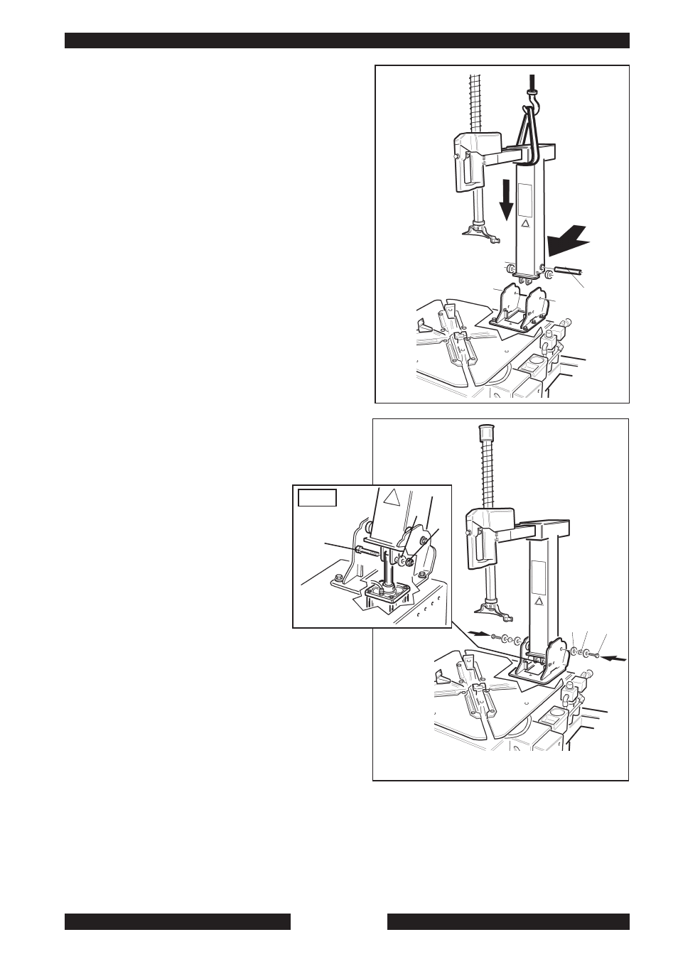
Inserire il palo verticale nel supporto della carcassa infilan-
dolo come indicato in fig. 5
Infilare il perno (2), la rondella (3) e la boccola conica (4)
serrare la vite (1). Fig. 5/6
Infilare il perno (5) comprensivo di rondella (6) per collegare il
cilindro ribaltamento e il palo come indicato in fig. 7
Avvitare il dado (7) avendo cura di non stringere troppo per
permettere al cilindro di poter lavorare correttamente e ri-
baltare il palo senza attriti.
Avvitare la vite e la rondella (10) per fissare la carenatura in
plastica come mostrato in Fig. 8.
5.2.1.1 Montaggio paletta e regolazione braccio
stalllonatore
Montare la paletta stallonatore (R) sul braccio stallonatore,
avendo cura che la rondella (15) resti dalla parte interna del
braccio e la rondella (16) dalla parte esterna.
Bloccare il tutto avvitando il dado autobloccante (17) sul per-
no della paletta.
Spostare la piastra (18) verso la parte esterna della macchina
(nel senso della freccia, fig. 9) e serrare in modo adeguato la
vite (19).
Fig. 5
5.2 PARTS ASSEMBLY
5.2.1 Arms assembly
Set the vertical arm into its housing on the
machine body, as shown in picture 5
Set the back screws (1), the bushes (2), the
washers (3) and tighten the nuts (4). Picture 6
Set pin (5) and washer (6) to join the tilting control cylinder to the
arm, as shown in picture 7.
Screw up nut (7) taking care not to tighten too much to enable
cylinder to operate correctly so tilting the arm without frictions.
Tighten screw and washer (10) to fix the plastic cover as shown in
picture 8.
5.2.1.1 Shovel assembly and arm setting
Set the blade (R) on the bead breaker arm taking care to place
washer (15) inside the arm and washer (16) outside.
Lock everything by tightening the self-locking nut (17) on the blade pin.
Fig. 9
Move plate (18) to the machine outside (see arrow, fig.9) and tighten
screw (19) properly.
Fig. 6
Fig. 7
5
6
7
2
1
3 4