Castle TSM-21 Serial 61064 and lower (Mead) Operator Manual User Manual
Page 19
When the magnet is placed against the reed switch then continuity should be registered.
If continuity IS registered then the distance between the mounted assembly needs to be
reduced by 1/16 of an inch on each side. First, loosen the screws holding the switch and
magnet to the mounting brackets. Squeeze them together and then tighten the screws to
reduce the distance.
If this still doesn't fix the problem then a new switch assembly (magnet and reed switch)
should be ordered.
The Foot Switch
Solution Steps:
The foot switch is a simple mechanical micro-switch operated by the pedal and a spring. The
switch is wired normally open, so a closure begins the cycle.
Turn the power to the machine off.
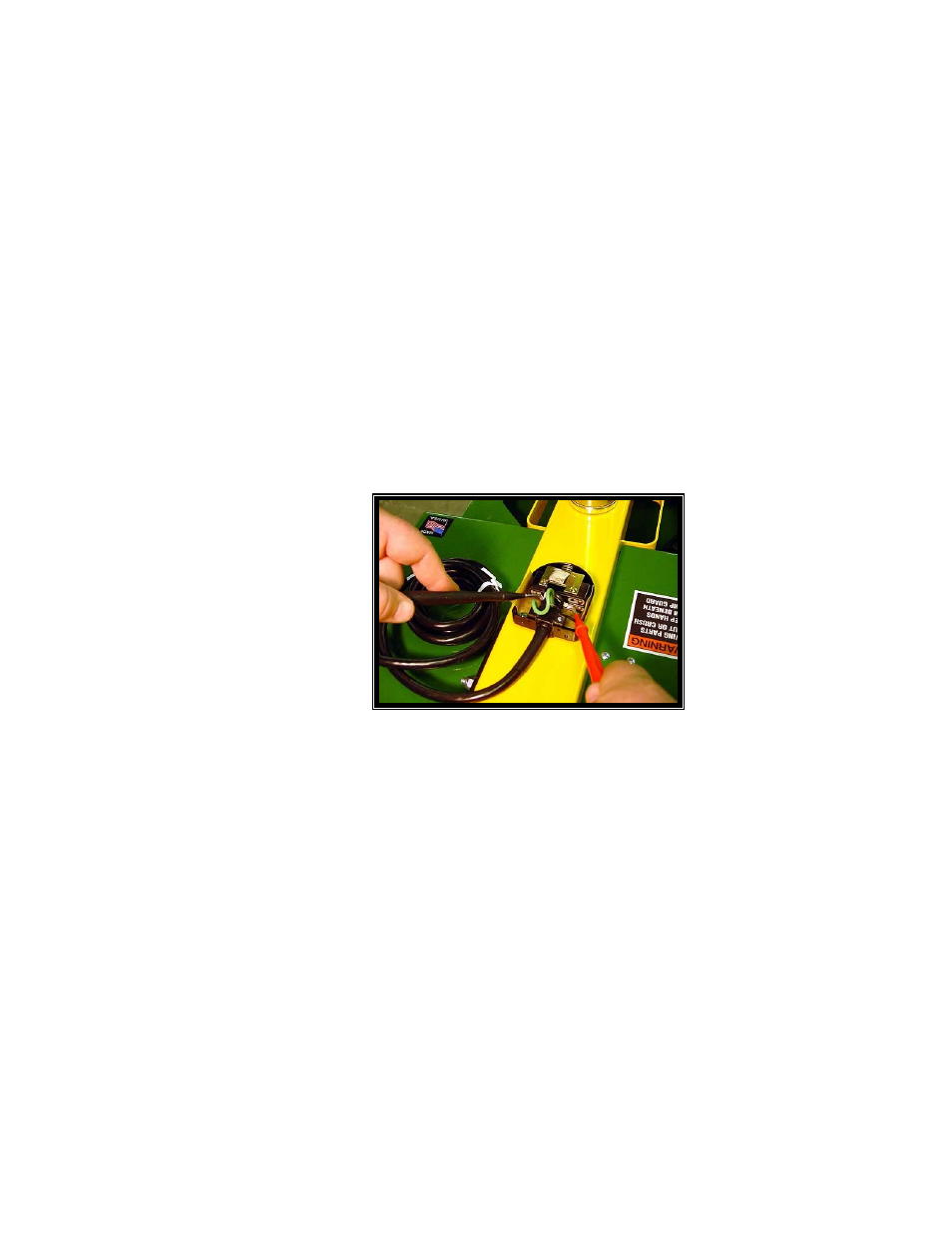
Figure 13
Turn the foot pedal and guard over and remove the two small screws that hold the pedal
to the guard.
Use a flat tip screwdriver to pry the pedal free from the yellow guard. It is held by a
silicone caulk.
Use a flat or phillips tip screw driver to remove the two screws on the left and right side
of the pedal. This will allow the pedal to come apart exposing the switch underneath.
The two leads of the Ohm Meter can be put to the connections on the switch while it is
still in the pedal. (Figure 13)
Press the switch to determine if the switch has continuity.
17