Schreiber Chillers 1000AC-MRI User Manual
Page 22
2.3.2. Place unit in position on wedges located at
four points (two below approximate center of driver
and two below approximate center of pump). Adjust
wedges to level unit. Level or plumb suction and
discharge flanges.
2.3.3. Make sure bedplate is not distorted and final
coupling alignment can be made within the limits of
movement of motor and by shimming, if necessary.
2.3.4. Tighten foundation bolts finger tight and build
dam around foundation. Pour grout under bedplate
making sure the areas under pump and motor feet
are solid. Allow grout to harden 48 hours before
fully tightening foundation bolts.
2.3.5. Tighten pump and motor hold-down bolts
before connecting the piping to pump.
3.1. Low static suction lift and short, direct, suction piping is
desired. For suction lift over 10 feet and liquid temperatures
over 120 F, consult pump performance curve for Net Positive
Suction Head Required.
3.2. Suction pipe must be as large as the suction connection
of the pump. Smaller size will degrade performance.
3.3. If larger pipe is required, and eccentric pipe reducer (with
straight side up) must be installed at the pump.
3.4. Installation with pump below source of supply:
3.4.1. Install full flow isolation valve in piping for
inspection and maintenance.
CAUTION
Do not us e suction isolation valve to throttle pump.
3.5. Installation with pump above source of supply:
3.5.1. Avoid air pockets. No part of piping should be
higher than pump suction connection. Slope piping
upward from liquid source.
3.5.2. All joints must be airtight.
3.5.3. Foot valve to be used only if necessary for
priming, or to hold prime on intermittent service.
3.5.4. Suction strainer open area must be at least
triple the pipe area.
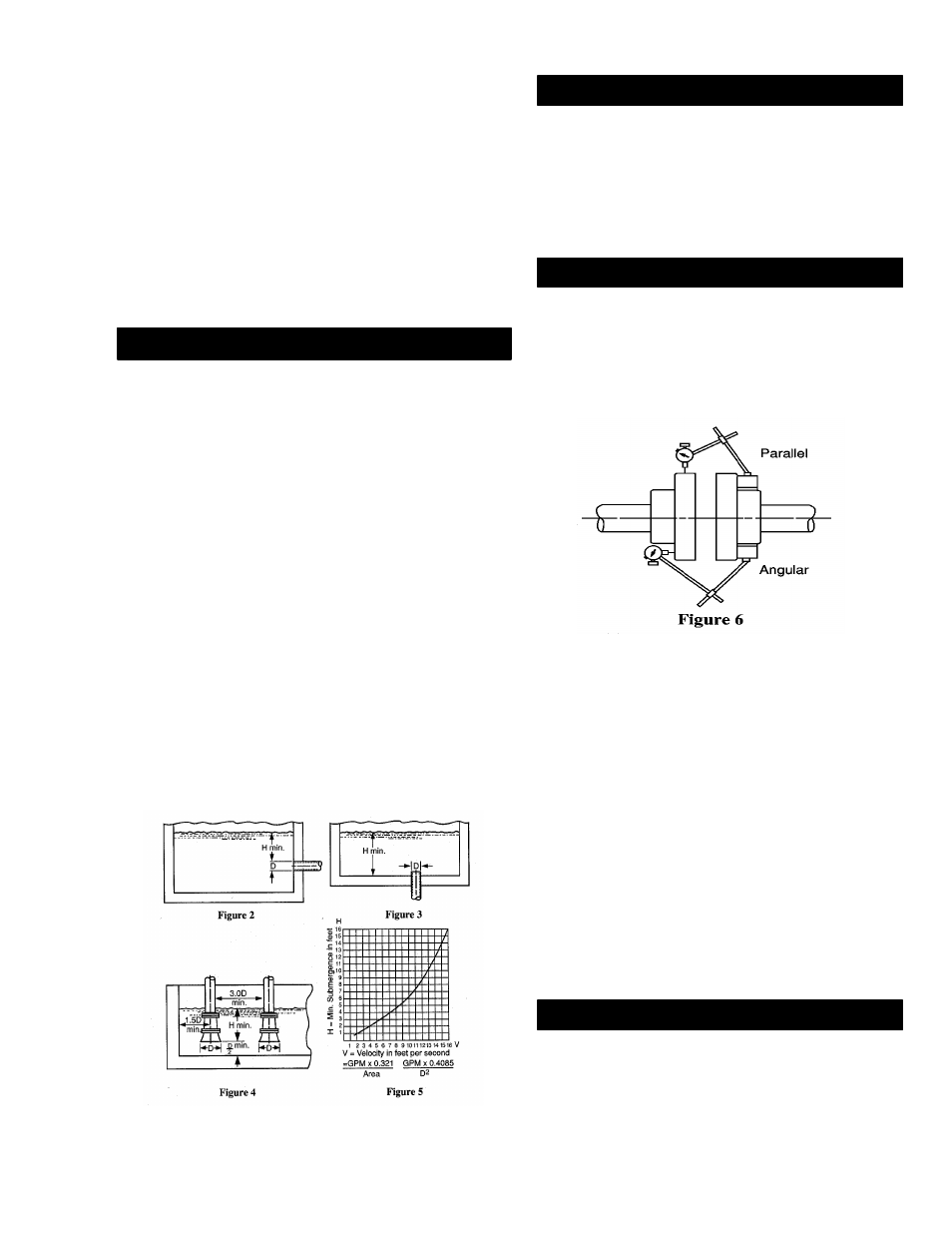
3.6. Size of the inlet from liquid source and minimum
submergence over inlet, must be sufficient to prevent air from
entering pump through vortexing. See figs. 2-5.
4.1. Arrangement must include a check valve located
between a gate valve and the pump. The gate valve is
for regulation of capacity, or for inspection of the pump
or check valve.
4.2. If an increaser is required, place between check
valve and pump.
4.3. Use 3-4 wraps of Teflon tape to seal threaded
connections.
5.1. Close-coupled Units:
5.1.1. No field alignment necessary.
5.2. Frame-Mounted Units:
5.2.1. Even though the pump-motor unit may
have a factory alignment, this could be
disturbed in transit and must be checked prior
to running.
5.2.2 Tighten all hold-down bolts before
checking the alignment.
5.2.3. If re-alignment is necessary, always
move the motor. Shim is required.
5.2.4. Parallel misalignment – shafts with axis
parallel but not concentric. Place a dial
indicator on one hub and rotate this hub 360°
while taking readings on the outside diameter
of the other hub. Parallel alignment occurs
when Total indicator reading is .005”, or less.
5.2.5. Angular misalignment – shafts with axiz
parallel but not concentric. Place dial
indicator on one hub and rotate this hub 360°
while taking readings on the face of the other
hub. Angular alignment is achieved when
Total Indicator Reading is .005”, or less.
5.2.6. Final alignment is achieved when
parallel and angular requirements are
satisfied with motor hold-down bolts tight.
CAUTION
Always recheck both alignments after making any
adjustment.
6.1. Correct rotation is right-hand (clockwise when
viewed from the motor end). Switch power on and off
quickly. Observe shaft rotation. To change rotation:
3. Suction Piping:
4. Discharge Piping:
5. Motor-To-Pump Shaft Alignment:
6. Rotation:
16