Conveyor tension setting, General information, Conveyor re-tensioning – DE-STA-CO Precision Link Conveyors 1.5, 3.0, 4.5, 6.0 Table Top; 6.0, 9.0 Heavy Duty User Manual
Page 9: Fig. 2. conveyor re-tensioning
CONVEYOR TENSION SETTING
GENERAL INFORMATION
To maintain and guarantee accuracy and
performance of the conveyor, CAMCO utilizes a
unique “chordal action compensating CAM”.
This CAM arrangement is state of the art in
precision link conveyor design. Spring actuated
tensioned conveyors utilizing either tail shaft or
secondary tensioning were rejected by CAMCO
because of the contribution to indexing inaccu-
racies.
Once the conveyor is properly tensioned at the
factory, no further adjustment is required in the
field for the duration of expected follower lift.
We are including instructions for adjustments,
should it become necessary to replace follow-
ers, or if the tension is lost because of extraordi-
nary conditions (i.e., EXTREME THERMAL
EXPANSION). It is recommended that CAMCO
factory be consulted prior to starting with the
actual adjustment. Failure to do so may void all
warranties for the conveyor.
CONVEYOR RE-TENSIONING
1. Read section in general information regard-
ing warranty.
2. Remove the radial guides at the take-up
end of the conveyor.
3. Loosen the take-up cam locking screws (4
per side) located in slotted holes in the main
frame portion of the conveyor. These are
located on both sides of the fitted key
section of the take-up cam.
The slots should be obvious on both sides
of the “over and under” conveyor. The slots
should be obvious on the top of the “carou-
sel” conveyor but may be more difficult to
locate on the bottom due to the base
mounting.
If a pedestal mount is used, the four
"forward-most” screws used to mount the
base to the main frame will be the take-up
cam locking screws.
On a heavy duty base design, clearance
holes will be provided to locate and access
these screws. It may also be necessary, on
a heavy duty base, to loosen the three end
support block mounting screws, located on
the bottom of the conveyor frame at the
extreme end.
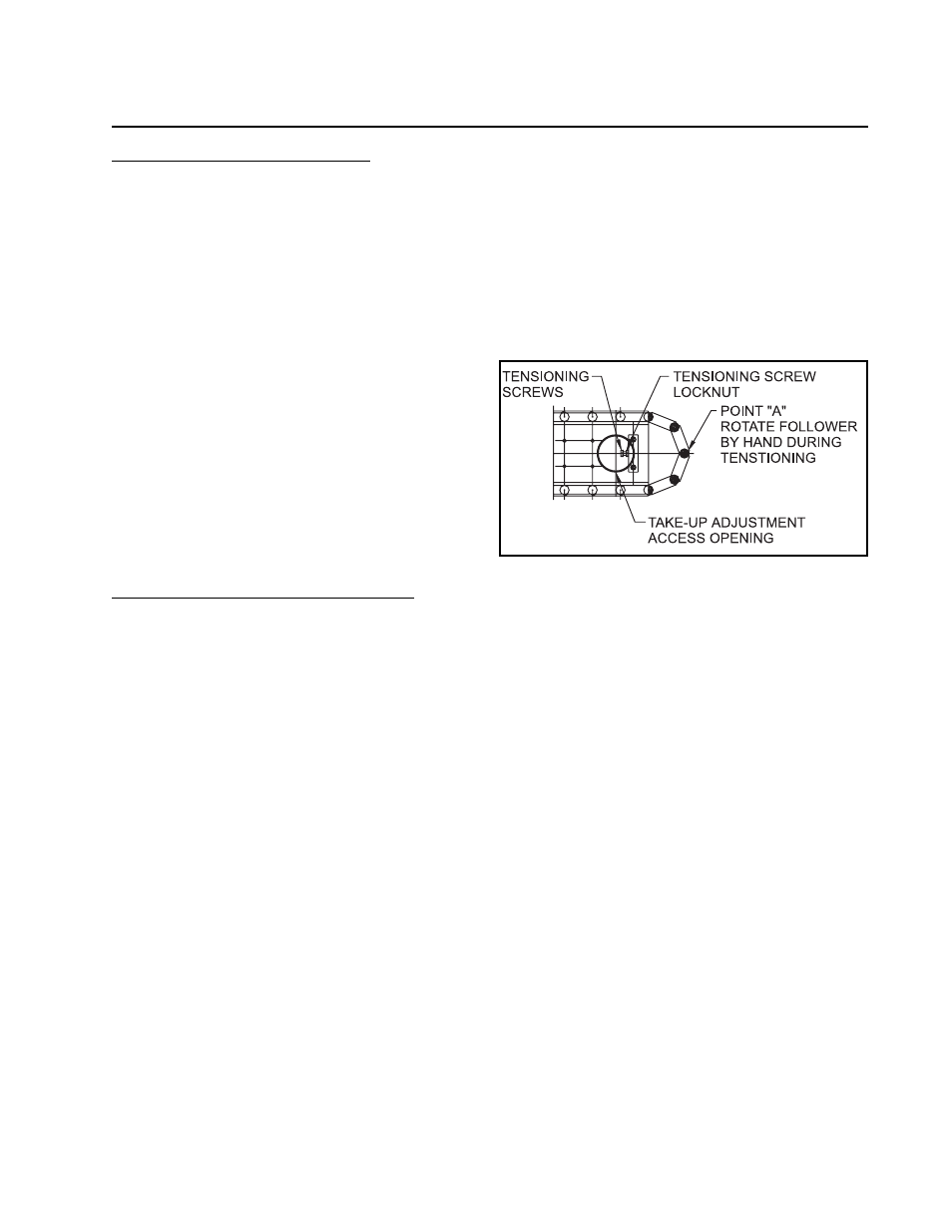
4. Once the locking screws have been loos-
ened, remove the round access cover for
the tension adjusting screw. Refer to
Figure 2.
Fig. 2. Conveyor re-tensioning.
5. Hand crank the index drive input reducer
until a link pin follower is positioned at the
high point of the take-up cam (point “A” as
shown in Figure 2).
6. Slowly tighten the tensioning screws, an
equal amount, until it becomes impossible to
turn the link pin cam follower, at point “A”, by
hand. At this point, it will still be easy to turn
the follower using pliers. If it is difficult with
pliers, you have overtightened.
7. Be sure that the followers at both ends of
the link pin have approximately. the same
loading. It is important to adjust the take-up
screws equally.
8. Tighten locknuts and locking screws (4 per
side).
9. Re-install the radial covers and tension
screw access cover.
8