Changing of precision link cam followers, Link pin followers (see pages 12 to 15), Link support followers – DE-STA-CO Precision Link Conveyors 1.5, 3.0, 4.5, 6.0 Table Top; 6.0, 9.0 Heavy Duty User Manual
Page 7: Fig. 1. removing link
CHANGING OF PRECISION LINK CAM FOLLOWERS
The changing of cam followers on CAMCO
Precision Link Conveyors is done by two meth-
ods, depending upon which follower is worn.
The procedure for changing the link pin follow-
ers (3) is different from the procedure for the
link support followers (10). (See Pages 12 to
15).
The following will describe the steps required
for each procedure:
LINK PIN FOLLOWERS
(See Pages 12 to 15)
1. Remove the radial guides from the drive
end of the conveyor.
2. Index the conveyor until the worn link pin
followers (3) are exposed at the end of the
conveyor.
3. Remove the retaining ring (4) holding
follower (3) on pin (2).
4. Remove the worn or damaged follower (3)
and replace.
CAUTION:
If shims (5) are used between
the link (9) and follower (3),
be sure to replace before
installing new follower.
5. Repeat until all worn or damaged followers
are replaced.
LINK SUPPORT FOLLOWERS
1. Remove the radial guides at the take-up
end of the conveyor.
2. Loosen the take-up cam locking screws (4
per side) located in slotted holes in the main
frame portion of the conveyor. These are
located on both sides of the fitted key
section of the take-up cam.
The slots should be obvious on both sides
of the “over and under” conveyor. The slots
should be obvious on the top of the “carou-
sel” conveyor but may be more difficult to
locate on the bottom due to the base
mounting.
If a pedestal mount is used, the four
"forward-most” screws used to mount the
base to the main frame will be the take-up
cam locking screws.
On a heavy duty base design, clearance
holes will be provided to locate and access
these screws. It may also be necessary, on
a heavy duty base, to loosen the three end
support block mounting screws, located on
the bottom of the conveyor frame at the
extreme end.
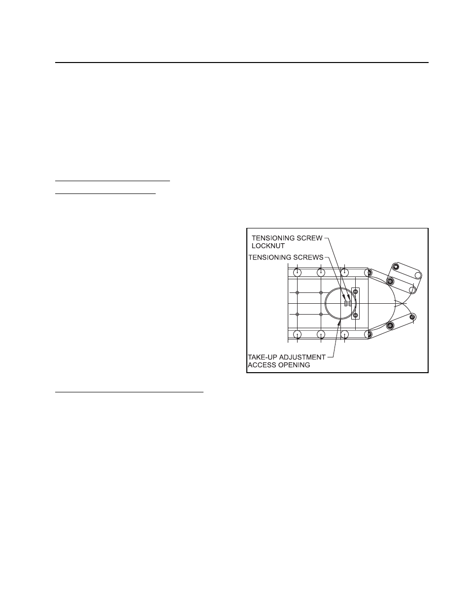
3. Once the locking screws have been loos-
ened, remove the round access cover for
the tension adjusting screw and back off the
tensioning screws two turns. Refer to
Figure 1.
Fig. 1. Removing link.
4. At this time, it will be possible to force the
take-up end towards the drive end enough
to provide slack in the link chain.
5. Hand crank the index drive input reducer
until the suspect link is positioned on the
radial end of the take-up cam.
6. Remove retaining rings (4) on the link pins
of the link to be removed.
6