Backplane layout – Chenbro RM31616 6Gb/s 16-port 3.5 mini-SAS Backplane(80H10331604A0) - Manual User Manual
Page 6
6
16-Port Mini-SAS 6Gb/s Backplane 80H10331604A0 ver. A0
User’s Manual
15Fl., No.150, Jian Yi Road, Chung Ho City, Taipei Hsien, Taiwan R.O.C.,
Tel: +886 2 82265500 Fax: +886 2 82265392 Email: [email protected]
w
w
w
.
c
h
e
n
b
r
o
.
c
o
m
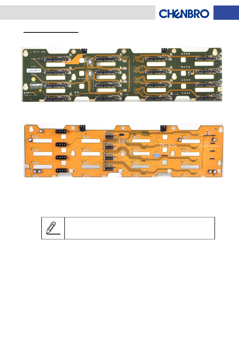
Backplane Layout
Front view ( HDD slot IN )
Rear View ( Host Connectors IN )
[CN011~CN161]
: Connect to 22-pin SATA-II or 29-pin SAS HDD 1~16
[F0104]
: HDD 1~4 Failure Signal Pin Header
[F0508]
: HDD 5~8 Failure Signal Pin Header
[F0912]
: HDD 9~12 Failure Signal Pin Header
[F1316]
: HDD 13~16 Failure Signal Pin Header
Connect the 4-pin HDD LED cable (26H113322-001) from CN2 to the
CATHODE of the HDD failure connector on RAID card. Refer to the RAID
card’s user manual for the detail pin definition.
[FAN1 / FAN2 / FAN3 / FAN4]
: 3-pin Fan connectors
[CN003 / CN004 / CN005 / CN006]
: Standard 4-pin Power connectors
[PC1]
: 4-pin Power connector for Optical Drive
[PC2]
: 4-pin Power connector for FDD
[CN002]
: Fan Signal Pin Header (connecting to LED Board)
[JP1]
: HDD Sequential Spin-up Enable / Disable
Spin-up Enable: Jumper set on pins 2 & 3 (Default factory setting, controlled by RAID / HBA)
Spin-up Disable: Jumper set on pins 1 & 2 (Controlled by HDD)
[JP2]
: Auto Detection For SAS/SATA HDD
Enable: Jumper set on pins , Disable: Remove Jumper
CB1
PC2
PC1
CB2
CB3
CB4
Fan1
F0104
F0508
F0912
F1316
Fan2
Fan3
Fan4
CN003
CN004
CN005
CN006
SW1
CN002
CN011
CN051
CN091
CN131
CN021
CN061
CN101
CN141
CN031
CN071
CN111
CN151
CN041
CN081
CN121
CN161
JP2
JP1