2 usm2 output scaling voltage, Table 4-1; usm2 output scaling samples, Signal definitions – Alpha Technologies USM2 User Manual
Page 20
20
©2000
™
704-587-B0-003 Rev.D
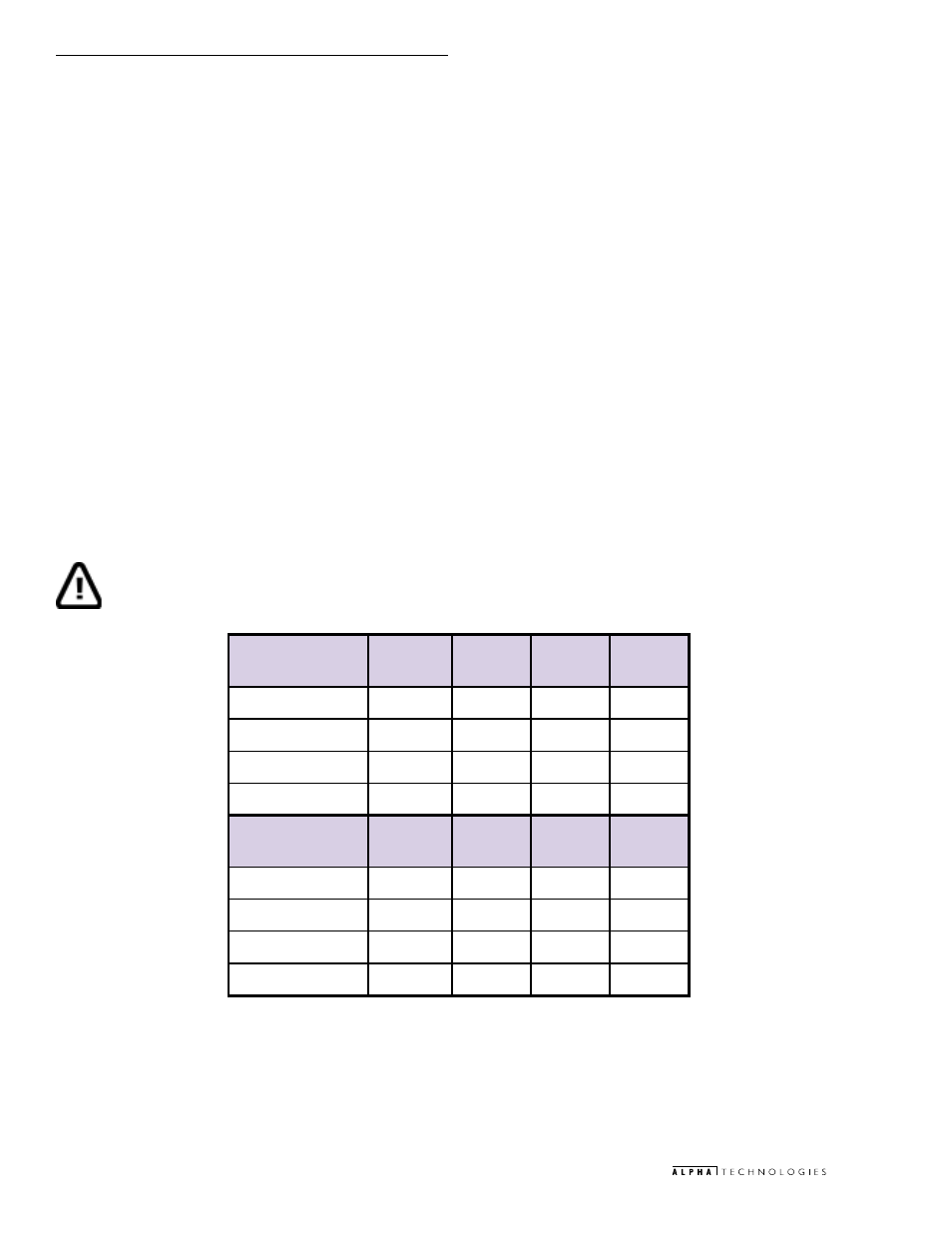
4.2 USM2 Output Scaling Voltage
USM Output Scaling Results:
Defines affect of XM2 operations on the USM2 output scalings.
Auxiliary DC Out (J3, pin 2)
Auxiliary DC output voltage is selected by JP1 and can provide: +5VDC, +15VDC, or +24VDC. This voltage
is used to provide transponder power.
Output Voltage level (J3, pin 4)
The scaling for 60VAC level is selected by JP2 and SW1(5) which can provide: 0.5VAC, 0.25VDC, or 0.15VDC
per VAC output.
Battery Voltage (J3, pin 5)
The scaling for Battery voltage is selected by SW1(1) and SW1(2) which can provide: 0.5VDC, 0.3VDC,
or 0.1VDC per VDC battery voltage.
AC Output Current #1 (J3, pin 8)
The scaling for AC output current #1 is selected by SW1(3) which will provide: 0.4VDC per ampere AC output.
AC Output Current #2 (J3, pin 13)
The scaling for AC output current #2 is selected by SW1(4) which will provide: 0.4VDC per ampere AC output.
IMPORTANT NOTE: In order for the USM2 to function correctly, OUTPUT (N) must be grounded to the chassis of the XM2
Series 2 power supply!
4. Signal Definitions
1
E
L
P
M
A
S
2
S
M
X
T
U
P
T
U
O
G
E
S
-
2
M
S
U
M
A
-
2
M
S
U
G
T
-
2
M
S
U
t
u
O
C
D
y
r
a
il
i
x
u
A
A
/
N
C
D
V
5
+
C
D
V
5
1
+
C
D
V
5
+
e
g
a
t
l
o
V
t
u
p
t
u
O
C
A
C
A
V
3
6
C
A
V
5
.
1
3
C
A
V
5
.
1
3
C
D
V
5
7
.
5
1
e
g
a
t
l
o
V
y
r
e
t
t
a
B
C
D
V
4
.
1
4
C
D
V
7
.
0
2
C
D
V
7
.
0
2
C
D
V
4
1
.
4
t
n
e
r
r
u
C
t
u
p
t
u
O
A
7
C
D
V
8
.
2
C
D
V
8
.
2
C
D
V
8
.
2
2
E
L
P
M
A
S
2
S
M
X
T
U
P
T
U
O
G
E
S
-
2
M
S
U
M
A
-
2
M
S
U
G
T
-
2
M
S
U
t
u
O
C
D
y
r
a
il
i
x
u
A
A
/
N
C
D
V
5
+
C
D
V
5
1
+
C
D
V
5
+
e
g
a
t
l
o
V
t
u
p
t
u
O
C
A
C
A
V
7
8
C
A
V
5
.
8
4
C
A
V
5
.
8
4
C
D
V
5
2
.
4
2
e
g
a
t
l
o
V
y
r
e
t
t
a
B
C
D
V
6
.
9
3
C
D
V
8
.
9
1
C
D
V
8
.
9
1
C
D
V
6
9
.
3
t
n
e
r
r
u
C
t
u
p
t
u
O
A
4
1
C
D
V
6
.
5
C
D
V
6
.
5
C
D
V
6
.
5
Table 4-1; USM2 Output Scaling Samples