Figure 3-2; jumper jp1, Figure 3-3; jumper jp2, Figure 3-2; jumper jp1 figure 3-3; jumper jp2 – Alpha Technologies USM2 User Manual
Page 18: Configuration, Continued, 1 usm2 configuration, Jumper jp1 reference: auxiliary dc voltage select
18
©2000
™
704-587-B0-003 Rev.D
3. Configuration
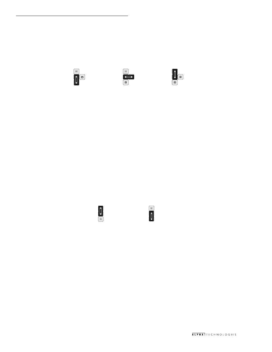
To select between fixed AC or variable DC scaling of the XM2 Series 2 output voltage, set the jumper as follows:
JP2 (1–2): AC Scaled XM2 Series 2 Output Voltage
This position selects AC scaling (0.5VAC per VAC Output Voltage).
JP2 (2–3): DC Scaled XM2 Series 2 Output Voltage
This position selects DC scaling. The actual scaling ratio is defined by SW1 (5).
3.1 USM2 Configuration,
continued
Jumper JP1 Reference: Auxiliary DC Voltage Select
The jumper designated JP1 is used to select the voltage of AUX DC delivered to the system’s transponder. This jumper
is configured by removing and placing the shorting connector on to one of the three positions (from the contact designated
as “C” for center).
To select between the various AUX DC output voltages supplied to the system’s transponder, set the jumper as follows:
JP1 (C–1):
Selects +5 V for the AUX DC output.
JP1 (C–2):
Selects +15 V for the AUX DC output.
JP1 (C–3):
Selects +24 V for the AUX DC output.
Jumper JP2 Reference: Output Voltage C or DC Scaling Select
The jumper designated JP2 is used to select either fixed scaling AC representation or variable scaling DC representation
of the XM2 Series 2 output voltage.
&
C–3
&
C–2
&
C–1
1–2
2–3
Figure 3-2; Jumper JP1
Figure 3-3; Jumper JP2