For xm series only, Alpha xm series power supply, Ab b important – Alpha Technologies XP-EDH-A2 User Manual
Page 2
2
745-838-C5-001 Rev. A
Power Supply
PWR
Power
14 PIN
US
DS
Battery
18 PIN
16 PIN
Fuse
WARNING:
3
INDICATOR
LAMP
REMOTE
STATUS
RELAY
STANDBY
1 2
OUTPUT
4
6
5
AC
B
LA
C
K
R
E
D
BATTERY
CONNECTOR
+
CIRCUIT
BREAKER
-
BATTERY
OFF
BLACK
RED
DOCSIS Transponder
AlphaNet
0A C4 36
ONLINE
System RF Cable in
AC Voltage Input
120V p/n 875-563-10
220V p/n 875-562-10
To Battery Harness
Power Supply Interface Cable
p/n 875-565-10
Black
wire
Yellow
wire
To Batteries
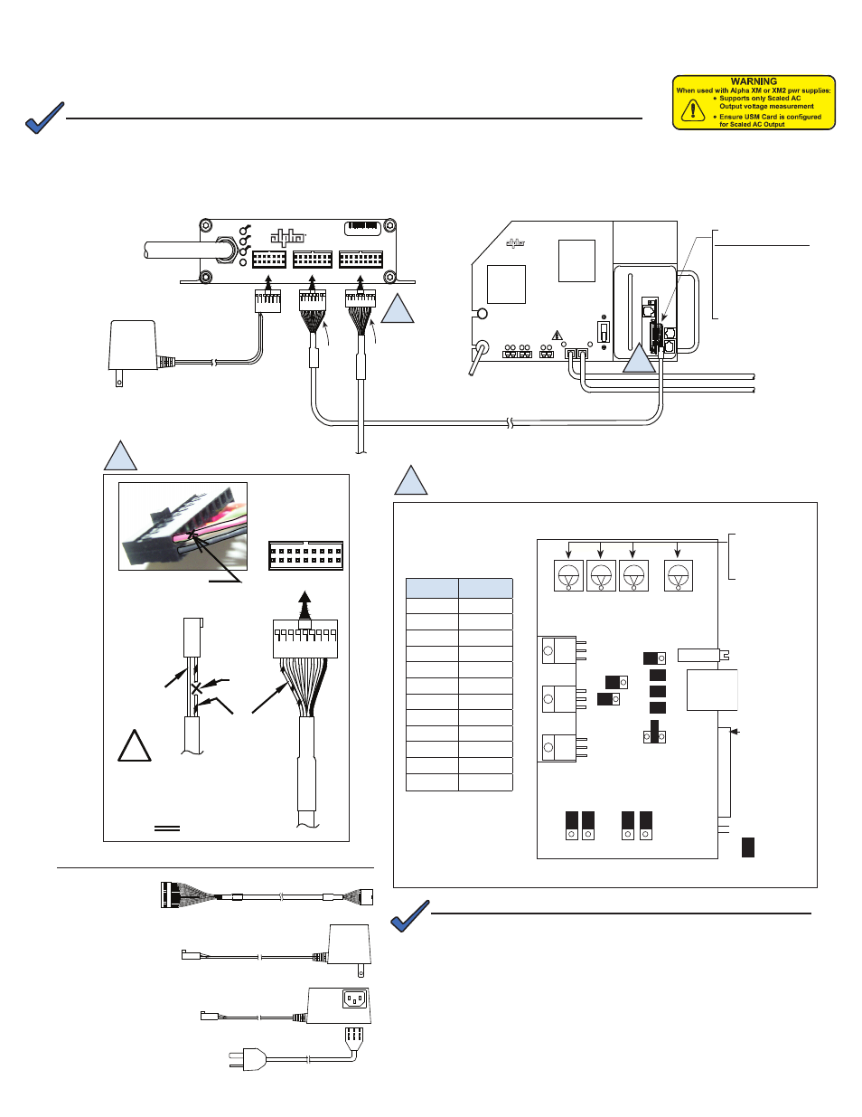
Jumper Position
P1
2-3
P2
open
P3
open
P4
closed
P5
closed
P6
closed
P7
5V
P8
1-2
P9
1-2
P13
1-2
P14
1-2
SW4
0
SW1
DC
1
2
3
18 PIN
Battery
Black
wire
Red/Green
wire
View
Side
Cut
Here
CUT AND REMOVE A PIECE OF
RED/GREEN WIRE IF PRESENT
FOR XM SERIES ONLY
!
CUT THE WIRE
IN UPPER LEFT POSITION
AS SHOWN. ANY WIRE COLOR.
Remove the USM and
set the jumpers as shown
below:
120VAC
TO
9VAC
CBL-PS-PWR-01-001
Alpha P/N 875-563-10
3 FT CORD
NEMA 6-15P
220V US
220VAC
IEC C13
9VAC
TO
CBL-PS-PWR-03-002
Alpha P/N 875-562-10
CBL-PS-INTFC-01-003
CBL-PS-INTFC-01-003
Alpha P/N 875-565-10
Or
Necessary Cables
Alpha XM Series Power Supply
Set to 0
(SWs 1,2,3 may not
be present on some
boards)
Potentiometer
Adjuster
RJ Connector
Power Supply
Interface
= Jumped
SW2
SW3
SW4
R8
1
2
1
2
1
2
1
1
1
P1
P2
P3
P4
P5
P6
P7
5V
24V 15V
P8 P9
P13 P14
AC
CUR
AC Volts
1
2
3
1
2
3
1
2
3
USM
3
PIN 1
A
A
B
B
Important!
Plug in the 13 pin
connector so the black
wire is in pin one (the top
pin) and two open pins
are left at the bottom for
tamper switch connection.
NOTE:
A chipset upgrade to the XM Inverter Module and/or USM Card may be required; contact Alpha for
more information.
Set the jumpers and calibrate the USM card before making cable connections and applying load.
1. Switch the battery breaker OFF.
2. Remove the Inverter Module from the power supply. See the power supply's technical manual for instructions.
3. Position jumpers and switches as shown below.
First, verify the transponder bears the warning label as shown at right. This indicates the unit is an XP-EDH-A2, and the
jump and switch settings described in this instruction will work properly.
NOTE:
The EDH-A2 calculates Output Voltage using AC Scaling as opposed
to the EDH-A which uses DC Scaling. This requires changes to the
USM card jumper settings and eliminates the need to calibrate the USM
potentiometer.