Alarm and signal wiring connections for cxcm, 11 alarm and signal wiring connections for cxcm – Alpha Technologies Cordex 48-1kW 19 User Manual
Page 29
Argus Technologies Ltd.
030-713-C0 Rev A WC
Printed in Canada. © 2008 Argus Technologies Ltd. ARGUS and CORDEX are trademarks of Argus Technologies Ltd. All Rights Reserved.
Page 15 of 23
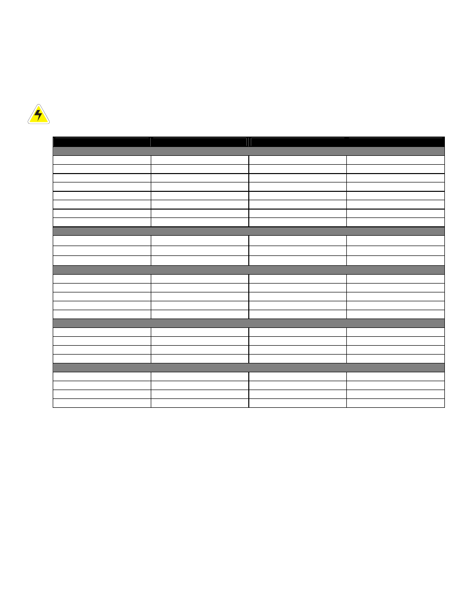
6.11 Alarm and Signal Wiring Connections for CXCM
NOTE: To aid the user with installation, frequent reference is made to drawings located at the rear of this manual.
Custom configurations may be detailed within the Argus power system documentation package.
For terminal block connections, the recommended wire sizes are 0.823 to 0.129mm
2
(#18 to #26 AWG) for the
temperature range of 0 to 50 deg. C (as per UL/CSA).
For insulation displacement receptacles, the recommended wire size is #18 AWG.
CAUTION: to reduce risk of fire, use only 0.129mm
2
(#26 AWG) or larger wire.
Terminal
Description
Signal Type
Range
Alarm Outputs –
Can be configured to de-energize on alarm (DOA) or energize on alarm (EOA).
#2-21,22(common)
K2, LVD2
NC/COM/NO (JP2)
60Vdc / 1A
#3-19,20(common)
K3, LVD3
NC/COM/NO (JP3)
60Vdc / 1A
#4-17,18(common)
K4, System Minor
NC/COM/NO (JP4)
60Vdc / 1A
#5-15,16(common)
K5, System Major
NC/COM/NO (JP5)
60Vdc / 1A
#6-13,14(common)
K6, AC Mains Hi-Low
NC/COM/NO (JP6)
60Vdc / 1A
#7-11,12(common)
K7, Not assigned
NC/COM/NO (JP7)
60Vdc / 1A
#8-9,10(common)
K8, Not assigned
NC/COM/NO (JP8)
60Vdc / 1A
#0-25,24,23
K0, System Fail Output*
NC/COM/NO
60Vdc / 1A
Digital Inputs –
See Table B for definitions of logic and system
P5-1,2
D1, Distribution Fuse (Alarm)
Pos (+) or Neg (-)
0—60Vdc
P5-3, P6-1
D2, Distribution CB (Alarm)
Pos (+) or Neg (-)
0—60Vdc
P6-2,3
D3, Battery CB (Alarm)
Pos (+) or Neg (-)
0—60Vdc
Analog Inputs and System Signals
E1
Battery -48V**
Neg (-)
20—60Vdc
J3 Ethernet
port
N/A
N/A
P1-2,1
K1, LVD1
Pos (+) / Neg (-)
0—60Vdc / 1A
P7-2,1
V1, Load Voltage
Pos (+) / Neg (-)
0—100Vdc
P8-2,1
I1, Load Current
Pos (+) / Neg (-)
±50mV
–
for List 120, add the following:
1-2
T1 (GP1), Temp Probe 1
Pos (+) / Neg (-)
0—20Vdc
, with power source
3-4
T2 (GP2), Temp Probe 2
Pos (+) / Neg (-)
0—20Vdc
, with power source
5-6
GP3, General Input 3
Pos (+) / Neg (-)
Not used
7-8
GP4, General Input 4
Pos (+) / Neg (-)
±60V,
bi-polar voltage
–
for List 124, consult the factory to add the following:
1-2
V3 (GP1), Voltage Input 3
Pos (+) / Neg (-)
0—60Vdc
3-4
V4 (GP2), Voltage Input 4
Pos (+) / Neg (-)
0—60Vdc
5-6
V5 (GP3), Voltage Input 5
Pos (+) / Neg (-)
0—60Vdc
7-8
T1 (GP4), General Input 4
Pos (+) / Neg (-)
0—20Vdc
, with power source
Table A–Signal wiring connections for CXCM
*
System Fail output relay is fail-safe and will de-energize during an alarm condition.
**
Battery –48V: connect to battery only when using a battery disconnect device
NOTE: To aid the user with installation, frequent reference is made to drawings located at the rear of this manual.
Custom configurations may be detailed within the Argus power system documentation package.