3 alarm connections, 4 grounding, 1 frame ground – Alpha Technologies DCP03 300A User Manual
Page 18: Alarm connections, Grounding
020-702-C0 Rev C WC
Page 12 of 16
5.3 Alarm Connections
Terminal blocks can accommodate wire sizes #16 to #26 AWG (1.5 to 0.14mm²).
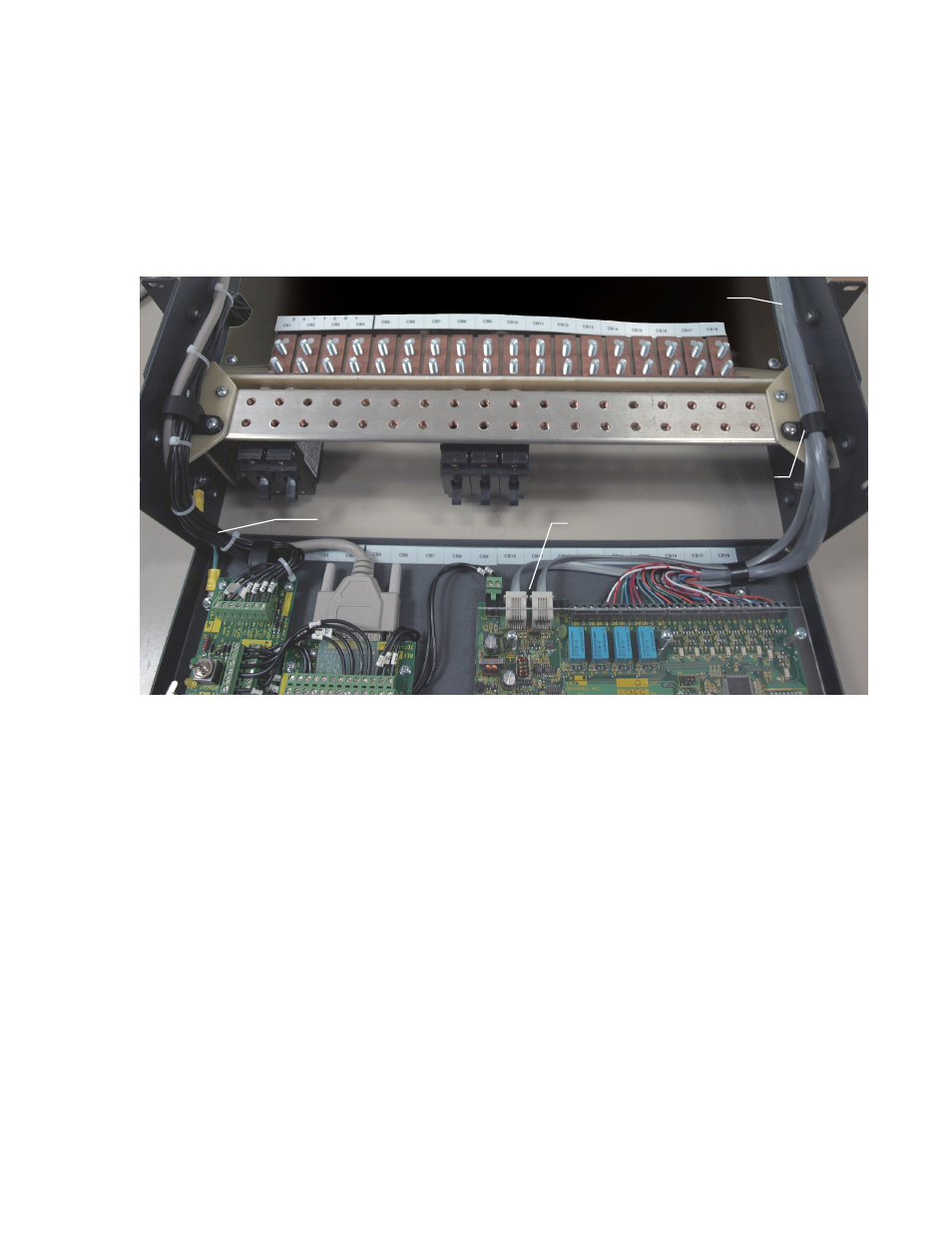
Route via wire-ways and use existing cable clamps to secure to existing (factory) wire harness along with
customer run signal wires. Ensure signal wires are routed along hinge point of front door so door opening and
closing won’t require excess wire slack. Refer to Figure 10 for wire routing example.
Terminal block connections for the internal alarm card, CXCI I/O, or CXCM2 I/O should be routed along the left
side of the DCP03 (looking at unit from front). Connections to the 4R/8D should be routed along the right hand
side of the DCP03. Refer to the customer connections (020-702-08) drawing at the rear of this manual for details
on terminal block assignments.
Figure 10–DCP03 wire routing example (List 74 and 79 shown)
(Photo is for reference only – subject to installation requirements)
5.4 Grounding
The isolated distribution center battery return bus (BRB) should be connected to the building master ground bus
(MGB) or floor ground bus (FGB) in a larger building. This acts as a system reference and as a low impedance
path to ground for surges, transients, noise, etc. The MGB or FGB should have a direct low impedance path to
the building grounding system. The cable from the distribution center to the MGB or FGB should be sized to
provide sufficient ampacity to clear the largest fuse or breaker on the distribution center, excluding the battery
protection fuse or circuit breaker. This is the minimum requirement; other factors including length of cable and
special grounding requirements of the load should also be factored in. The insulated cable should be equipped
with two-hole crimp type lugs and should not have any tight bends or kinks.
The distribution center frame must also be connected to the MGB or FGB. This is done for personnel safety and
to meet many Telco grounding requirements. Each bay should have its own frame ground connection. The
minimum recommended wire size is #2 AWG (35mm²).
5.4.1 Frame Ground
The DCP03 is grounded utilizing screws/bonding washers to the relay rack then to the main grounding bus using
#2 AWG (35mm²) insulated cable.
System Internal and
CXCI wire routing
Cable clamp
4R/8D ADIO or 8R/8D 8DIO wire routing
4R/8D ADIO or 8R/8D 8DIO
CAN ports