2 distribution cabling, 3 breaker output (hot) connections, 4 breaker return (ground) connections – Alpha Technologies DCP03 300A User Manual
Page 17
020-702-C0 Rev C WC
Page 11 of 16
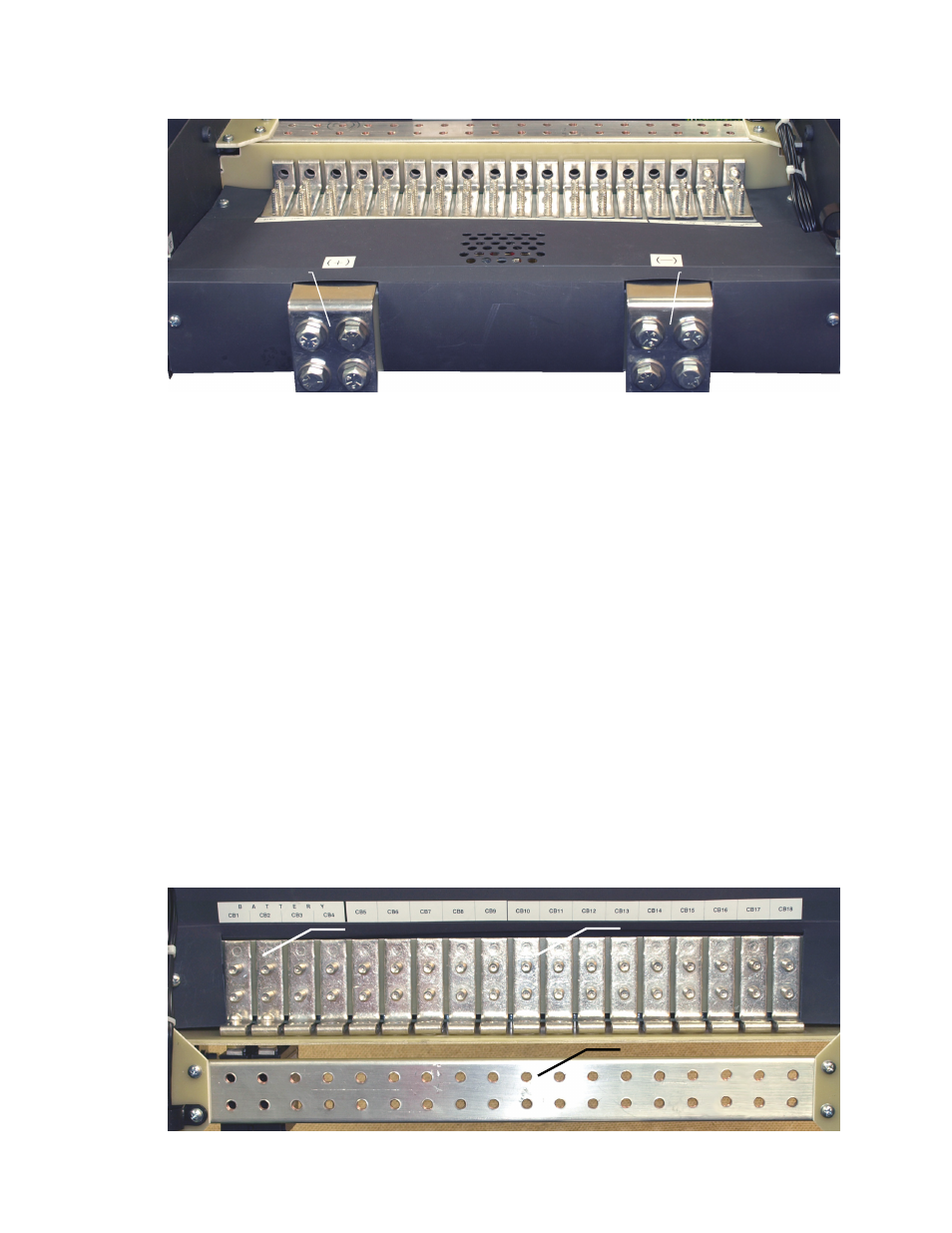
NOTE: Bus bar inputs are fixed for hot and return placement. Labels indicating polarity will be reversed when configured
for 48Vdc positive ground versus 24Vdc negative ground.
Figure 8–Rear view of DCP03 bus bar input
5.2.2 Distribution Cabling
Refer to guidelines supplied with the load equipment. Typically distribution cables are sized to provide a 0.5V loop
drop at full load as well as meeting ampacity requirements of the protection fuse or circuit breaker.
Distribution cabling must be terminated with 1/4"–5/8"C lugs for connecting to DCP03.
5.2.3 Breaker Output (Hot) Connections
Connect breaker (hot) output connections before connecting the breaker returns. Secure two hole lugs to the 1/4"
studs (on 5/8" centers) using the supplied hardware with the DCP03. Cables should run directly out the rear of the
distribution center. Refer to Figure 9.
5.2.4 Breaker Return (Ground) Connections
Connect breaker (ground) output connections to the DCP03 ground bar. Secure two hole lugs to the 1/4" holes
(on 5/8" centers) using the supplied hardware with the DCP03. Cables should run directly out the rear of the
distribution center above the breaker (hot) output cables. Refer to Figure 9.
5.2.5 Battery Breaker Connections (List 88 Configuration)
Connect battery breaker (hot) connections first using same guidelines as the load cable installation. Connect
battery ground connections using same guidelines as load returns. Cables should run directly out the rear of the
distribution center above the breaker (hot) output cables. Refer to Figure 9.
Figure 9–Battery, load, and return connection locations (List 88 configuration shown)
DCP03 input bar (return)
DCP03 input bar (hot)
Load breaker (hot) connection
System return (ground) bar
Battery (hot) connection