Installation, Nstallation, 1 safety precautions – Alpha Technologies 32-0-10A Fuse Panel User Manual
Page 11: 2 tools required, 3 preparation/mounting
A
RGUS
T
ECHNOLOGIES
32-0-10A
F
USE
P
ANEL
020-103-C0 R
EV
B
P
AGE
3 of 6
3 I
NSTALLATION
This section is provided for qualified personnel to install the 32-0-10A Fuse Panel.
3.1 Safety
Precautions
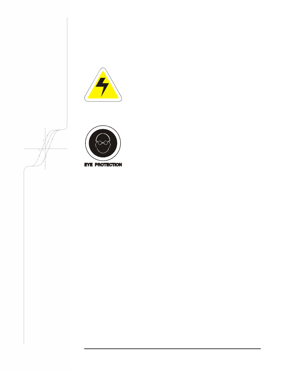
WARNING
Hazardous voltages are present at the input of the
rectifier systems. The DC output from the rectifiers
and the battery system though not dangerous in
voltage has a high short circuit current capacity that
may cause severe burns and electrical arcing.
Before working with any live battery or power system/distribution center the follow-
ing precautions should be followed:
Remove all metallic jewelry; e.g. watches, rings, eyeglasses,
necklaces.
Safety glasses with side shields must be worn at all times.
Metallic tools must be factory insulated or insulated using the following method:
1. Apply one layer of half-lapped rubber splicing tape
2. Cover the rubber splicing tape with two half-lapped layers of vinyl tape
Installer should follow all applicable local rules and regulations for electrical and bat-
tery installations; i.e. CSA, UL, CEC, NEC, and local fire codes.
3.2 Tools
Required
• Philips head screwdriver, #3 (tip size ¼”)
• Slot head screwdriver (blade size ⅛”)
• Cutters and wire strippers (#14 to #22 AWG) [0.34 to 2.5 mm
2
]
• Digital voltmeter equipped with test leads.
3.3 Preparation/Mounting
The 32-0-10A Fuse Panel occupies a single vertical rack space. The rack mounting
“ears” may be center or flush mounted (see Outline Drawing 020-103-06) in a 19” or
23” EIA standard relay rack.
Orientate the ears as desired and secure the Fuse Panel to the rack using two #12-
24x½” screws on each side. A captive type of drive, such as the Philips head, is pre-
ferred to reduce the possibility of slippage and scratching of the unit’s exterior.
The Fuse Panel must
be mounted in a clean
and dry environment.