3 replacing the cxcm4 module – Alpha Technologies Cordex HP CXRF 48-12kW User Manual
Page 34
9400000-J0 Rev C
32
10.3 Replacing the CXCM4 Module
WARNING!
Before removing a CXCM4 from a live system, an external LVD override is required to
avoid a disruption of service.
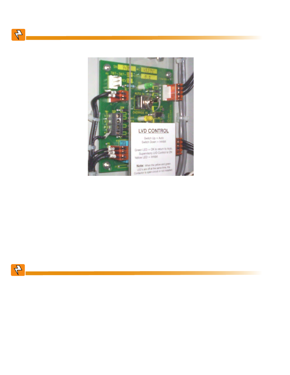
The LVD Control functions can be hardwired directly from the assigned relay output to an optional LVD override
control and distribution alarm card (707-307-20).
1. Place the LVD Control switch to the OVERRIDE IN position to keep the LVD contactor engaged.
2. To remove a module, loosen the screw on the bottom of the faceplate. Slide the module away from the rear
connectors and out of the shelf.
3. Place the new controller on the shelf bottom and slide the module into the CXCM4 connection interface
(inside of the shelf, see drawing 747-271-08). Do not force the module into position if it does not seat properly.
All modules are keyed to ensure that the correct module (voltage/polarity) type is used.
4. Apply pressure on the metal faceplate to engage the rear connectors.
5. Tighten the screw on the bottom of the faceplate to secure the module to the shelf.
WARNING!
Do not leave the switch in the OVERRIDE IN position. Doing so may result in a complete
discharge of the batteries during a power failure.
6. To allow the CXC to resume automatic control of the LVD contactor, check that the green AUTO IN LED is
illuminated confirming that the CXC will keep the LVD contactor engaged.
7. Switch the LVD control switch back to the AUTO IN position.
Figure 8 — LVD override control and distribution alarm card