Alpha Technologies Cordex Controller Panel Mount_Rack Mount User Manual
Page 20
Argus Technologies Ltd.
018-587-C0 Rev A WC
Printed in Canada. © 2008 Argus Technologies Ltd. ARGUS and CORDEX are trademarks of Argus Technologies Ltd. All Rights Reserved.
Page 10 of 19
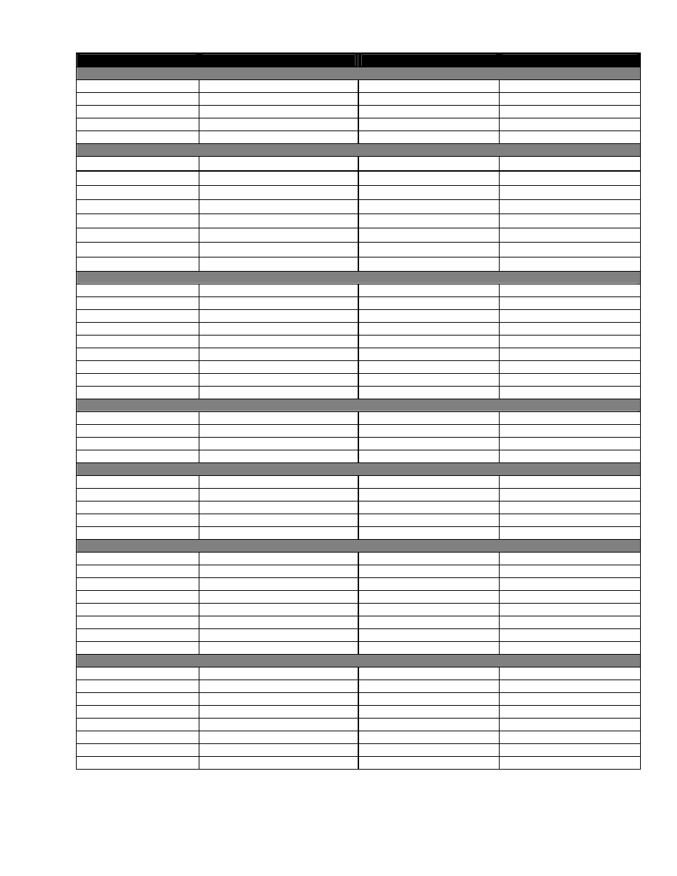
Terminal
Description
Signal Type
Range
Analog Inputs and System Signals
3 and 4; V2
Battery (Charge) Voltage
Pos (+) / Neg (-)
0—100Vdc
13 and 14; I1
Load (Discharge) Current
Pos (+) / Neg (-)
±50mV
64, 65, and 66; DCCT
DCCT Power Supply
Pos (+) / Gnd / Neg (-)
±15Vdc / 100mA maximum
67 and 68; B PWR
Secondary Power
Pos (+) / Neg (-)
20—60Vdc
69 and 70; A PWR
Power
Pos (+) / Neg (-)
20—60Vdc
Digital Inputs –
See Table A for definitions of logic and system
21 and 22; D1
Distribution Fuse/Circuit Breaker
Pos (+) or Neg (-)
0—60Vdc
23 and 24; D2
Battery Fuse/Circuit Breaker
Pos (+) or Neg (-)
0—60Vdc
25 and 26; D3
LVD Manual In
Pos (+) or Neg (-)
0—60Vdc
27 and 28; D4
LVD Manual Out
Pos (+) or Neg (-)
0—60Vdc
29 and 30; D5
Converter Fail
Pos (+) or Neg (-)
0—60Vdc
31 and 32; D6
Converter I/P Breaker Trip
Pos (+) or Neg (-)
0—60Vdc
33 and 34; D7
Unassigned
Pos (+) or Neg (-)
0—60Vdc
35 and 36; D8
Unassigned
Pos (+) or Neg (-)
0—60Vdc
Alarm Outputs –
Can be configured to de-energize on alarm (DOA) or energize on alarm (EOA).
37, 38, and 39; K1
LVD1
NC/COM/NO
60Vdc / 1A
40, 41, and 42; K2
LVD2
NC/COM/NO
60Vdc / 1A
43, 44, and 45; K3
LVD3
NC/COM/NO
60Vdc / 1A
46, 47, and 48; K4
System Minor
NC/COM/NO
60Vdc / 1A
49, 50, and 51; K5
System Major
NC/COM/NO
60Vdc / 1A
52, 53, and 54; K6
AC Mains Hi/Low
NC/COM/NO
60Vdc / 1A
55, 56, and 57; K7
Unassigned
NC/COM/NO
60Vdc / 1A
58, 59, and 60; K8
Unassigned
NC/COM/NO
60Vdc / 1A
61, 62, and 63; K0
System Fail Output*
NC/COM/NO
60Vdc / 1A
–
for List 120, add the following:
1 and 2; V1
Load (Discharge) Voltage
Pos (+) / Neg (-)
0—100Vdc
5 and 6; GP1
Temp Probe 1
Pos (+) / Neg (-)
0—20Vdc
, with power source
7 and 8; GP2
Temp Probe 2
Pos (+) / Neg (-)
0—20Vdc
, with power source
11 and 12; GP4
Bipolar Voltage
Pos (+) / Neg (-)
±60V
–
for List 124, add the following:
1 and 2; V1
Voltage 1
Pos (+) / Neg (-)
0—100Vdc
5 and 6; GP1
Voltage 3
Pos (+) / Neg (-)
0—60Vdc
7 and 8; GP2
Voltage 4
Pos (+) / Neg (-)
0—60Vdc
9 and 10; GP3
Voltage 5
Pos (+) / Neg (-)
0—60Vdc
11 and 12; GP4
Temp Probe 1
Pos (+) / Neg (-)
0—20Vdc
, with power source
–
for List 125, add the following:
1 and 2; V1
Load (Discharge) Voltage
Pos (+) / Neg (-)
0—100Vdc
5 and 6; GP1
Temp Probe 1
Pos (+) / Neg (-)
0—20Vdc
, with power source
7 and 8; GP2
Temp Probe 2
Pos (+) / Neg (-)
0—20Vdc
, with power source
9 and 10; GP3
Bipolar Voltage
Pos (+) / Neg (-)
±60V
11 and 12; GP4
Bipolar Voltage
Pos (+) / Neg (-)
±60V
15 and 16; I2
Battery (Charge) Current
Pos (+) / Neg (-)
±50mV
17 and 18; I3
Current Input 3
Pos (+) / Neg (-)
±50mV
19 and 20; I4
Current Input 4
Pos (+) / Neg (-)
±50mV
–
for List 129, add the following:
1 and 2; V1
Load (Discharge) Voltage
Pos (+) / Neg (-)
0—100Vdc
5 and 6; GP1
Temp Probe 1
Pos (+) / Neg (-)
0—20Vdc
, with power source
7 and 8; GP2
Temp Probe 2
Pos (+) / Neg (-)
0—20Vdc
, with power source
9 and 10; GP3
Temp Probe 3
Pos (+) / Neg (-)
0—20Vdc
, with power source
11 and 12; GP4
Temp Probe 4
Pos (+) / Neg (-)
0—20Vdc
, with power source
15 and 16; I2
Current Input 2
Pos (+) / Neg (-)
±50mV
17 and 18; I3
Current Input 3
Pos (+) / Neg (-)
±50mV
19 and 20; I4
Current Input 4
Pos (+) / Neg (-)
±50mV
Table B–Wiring connections for CXCP/CXCR
*
System Fail output relay is fail-safe and will de-energize during an alarm condition.