Alpha Technologies BPT Series Bypass Transformer User Manual
Page 11
3.2 Bypass Switch Installation
CAUTION: The installation and testing of the Bypass Switch must be performed only by
qualified personnel familiar with installing electrical equipment. This must be done in
accordance with the rules and regulations of local and national electrical codes.
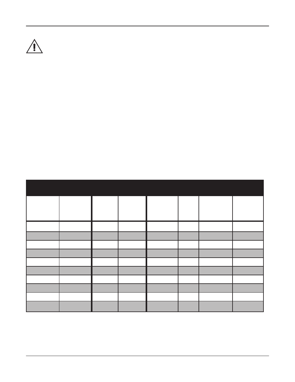
The installation of a bypass circuit breaker is required. To select the proper size circuit breaker
refer to Table 2.
Procedure:
1. Select an appropriate location for the Bypass Switch (and Bypass Transformer if required).
The Bypass Switch can be mounted to a wall close to the UPS. The Bypass Transformer
can be either wall or floor mounted.
2. Connect the BPS (and BPT if required) to the UPS and utility following the schematic wiring
diagram applicapable to your configuration as specified in Table 1. Refer also to Table 2 to
select the proper size circuit breaker and wire gauge.
3. Before placing the BPS-UPS into service, perform the test procedure outlined in Section
4.1 on page 9 of this manual. It is important that both sources of power are “in phase” to
provide trouble free Bypass Switch operation.
Table 2 : Bypass Circuit Breaker Current Rating
UPS Model
Systems Without
Bypass Transformer
Systems With Bypass Transformer
Max UPS
Output
Current (Amps)
Bypass
CB Rating
(Amps)
Wire Size
(AWG)
Input Rating
of BPT @
208 Vac
(Amps)
Bypass
CB
Rating
(Amps)
Wire Size for
208 Vac or
240 Vac Loads
(AWG)
Wire size for
120 Vac Load
(AWG)
CFR 1500
(or smaller)
12.5
15
#14
8
15
#14
#14
CFR 2000
17
20
#12
11
15
#14
#12
CFR 2500
21
30
#10
13
15
#14
#10
CFR 3000
25
40
#8
16
20
#12
#8
CFR 4000
33
50
#6
21
30
#10
#6
CFR 5000
41
60
#6
27
40
#8
#6
CFR 7.5K
36
50
#6
36
50
#6
N/A
CFR 10K
48
60
#6
48
60
#6
N/A
CFR 15K
72
90
#3
72
90
#3
N/A
1600 EP
18KVA
75
90
#3
75
90
#3
N/A
Notes:
Current ratings for CFR 5000 and smaller units are based on 120V rated output. This is because the rated output of L1 is
capable of supplying the full 120V current. Current ratings for CFR 7.5K - 15K are based on the maximum current rating for L1
and L2 combined (refer to the appropriate Operator’s Manual for further details).
Wire sizes are based on three current carrying copper conductors rated at 75 deg. C and are guidelines only. Always follow
your local electrical code.
Installation
Doc# 020-133-B0 Rev. 01 / 07
7