Ac load centre (example 2), Nl1 l2 – Alpha Technologies Te25xh User Manual
Page 20
Argus Technologies Ltd.
029-006-C0 Rev D WC
Printed in Canada. © 2006 Argus Technologies Ltd. ARGUS is a registered trademark of Argus Technologies Ltd. All Rights Reserved.
Page 10 of 15
7.2.2
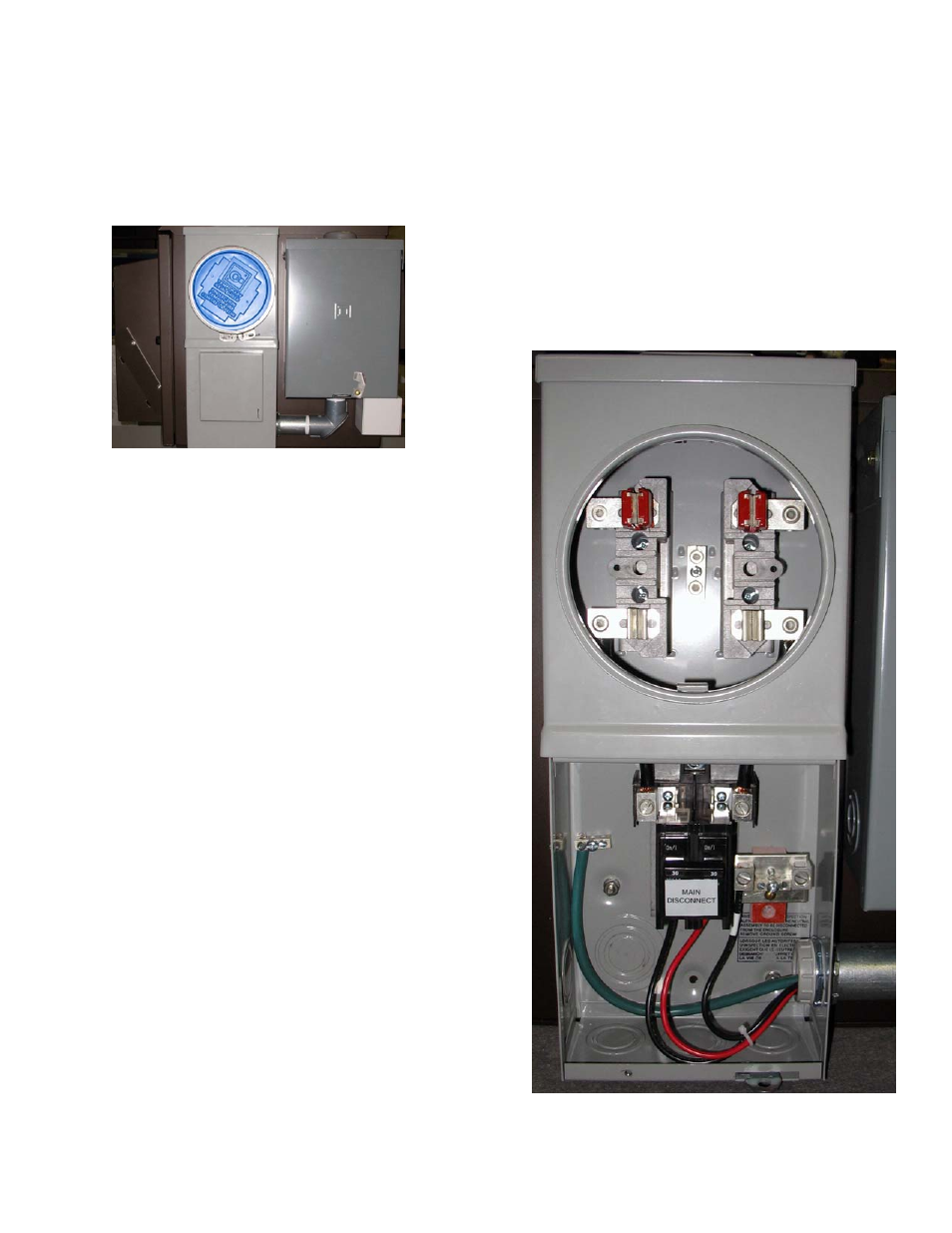
AC Load Centre (Example 2)
This sample system is configured with a 100A 8-position load centre and a 100A combination meter socket with
provision for 2-pole main breaker (comes equipped with a 30A breaker).
Figure 9–Side view of example 2
NOTE: See schematic at the rear of this manual.
1. Locate the combination meter socket on the side of the
enclosure and remove the front cover panel(s) to
access the meter socket and circuit breaker interior
assembly.
2. If this combination meter socket is to be used as the
primary service entrance (when main breaker is
installed), connect bonding wire between the neutral
bus bar assembly and the equipment ground bus bar.
3. Remove appropriate knockout or use hub on the top of
box to accept the power conduit.
4. Install conduit and feed power cables into the
combination meter socket.
5. Locate the line input terminal lugs (L1 and L2) on the
meter socket base, the neutral bus bar(s) and the
equipment ground bar. Refer to Figure 10.
6. Connect the black wire to L1.
7. Connect the red wire to L2.
8. Connect the white wire to the neutral bus bar located
at meter socket base (top). Then connect a white wire
from meter socket neutral bus bar to neutral bus bar
located in main breaker section (bottom).
9. Connect the green or bare copper wire to the
equipment ground bar.
10. Label all wires as necessary.
11. Replace front cover panel(s).
Figure 10–Combination meter socket
AC input power connection terminals
N
L1 L2
N
G