Ac input power, Ac load centre (example 1), L1 l2 n g – Alpha Technologies Te25xh User Manual
Page 19
Argus Technologies Ltd.
029-006-C0 Rev D WC
Printed in Canada. © 2006 Argus Technologies Ltd. ARGUS is a registered trademark of Argus Technologies Ltd. All Rights Reserved.
Page 9 of 15
7.2
AC Input Power
Verify electrical codes prior to installation. Codes may vary and contain specific conduit and wire
sizes for AC input power connections.
Connection to utility power must be approved by the local utility before installing the power
supply.
7.2.1
AC Load Centre (Example 1)
This sample system is configured with a 100A 8-position
load centre and a 70A 2-pole main disconnect equipped
with a 30A breaker.
Figure 7–Side view of example 1
NOTE: See schematic at the rear of this manual.
1. Locate the 2-pole main disconnect AC load centre at
the side of the enclosure and remove the front cover
panel to access the circuit breaker interior assembly.
2. Remove appropriate knockout or use hub on the top of
box to accept the power conduit.
3. Install conduit and feed power cables into the AC load
centre.
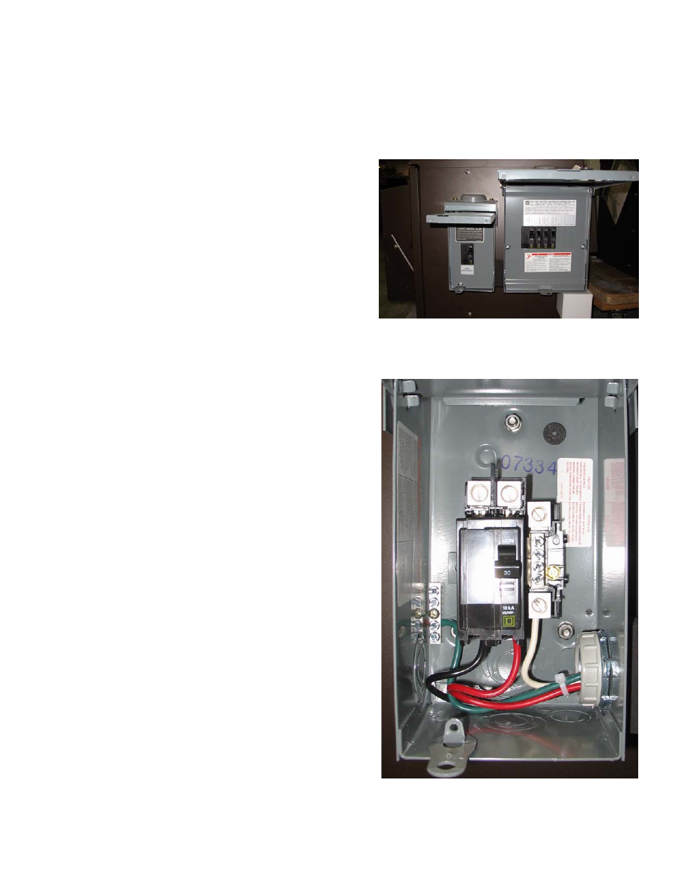
4. Locate the line input terminal lugs (L1 and L2) on the
main circuit breaker, the neutral bus bar and the
equipment ground bar. Refer to Figure 8.
5. Connect the black wire to L1.
6. Connect the red wire to L2.
7. Connect the white wire to the neutral bus bar.
8. Connect the green or bare copper wire to the
equipment ground bar.
9. Label all wires as necessary.
10. Replace front cover panel.
Figure 8–Connections to AC input
main disconnect breaker
L1 L2
N
G