It6 w, Ount – Alera Lighting IT6 - Wall Mount User Manual
Page 2
2-6
T
F
IXTURE
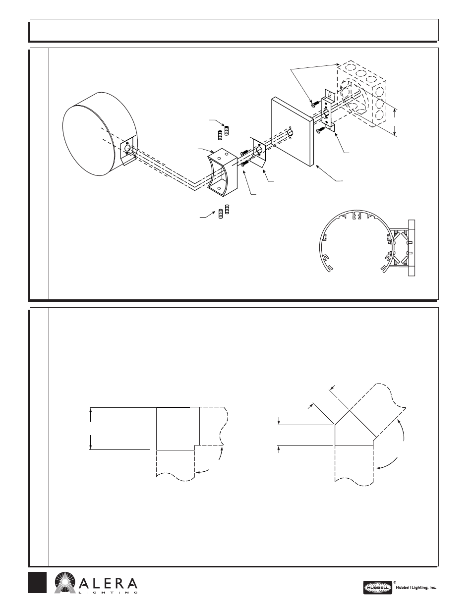
C
ONNECTIONS
C
ORNER
D
IMENSIONS
T
ECHNICAL
I
NSTALLATION
D
ATA
IT6 W
ALL
M
OUNT
Set screws
Support arm
Screw #10-24 .500
Set screws
Wall cleat
Wall plate
Wall bracket
2
3
⁄
4
″ plaster
ring
mounting
Junction box, plaster ring,
and mounting screws by
installing contractor
1) Attach wall bracket to plaster ring using plaster ring screws. (Pull service
through center hole)
2) Attach wall plate and wall cleat to wall bracket with two #10-24 X .500
round head machine screws provided.
3) Secure support arm to wall cleat by driving two
1
⁄
4
-20 X .500 recessed
socket head set screws (provided with kit) behind flanges of wall cleat.
4) Make service lead connection to ballast leads and ground inside fixture.
AL 10/07
90
°
135
°
90
°
135
°
8
″
4
1
⁄
2
″
4
1
⁄
2
″
701 Millennium Blvd
Greenville SC 29607 • (864) 678-1000
www.aleralighting.com
We are architectural fluorescent lighting
Subject to change without notice.
- AL1072 - Installed Daylight Sensors Guide (7 pages)
- AL1066 - A+CLASS Quick Start Guide (2 pages)
- LM6R G SG (2 pages)
- LM6R F (2 pages)
- CV (2 pages)
- Curv End Cap Flyer (1 page)
- Lutron EcoSystem (1 page)
- Phillips LuxSense (1 page)
- CV - Arch Sensors (2 pages)
- CPLS (2 pages)
- CPLS - Arch Sensors (2 pages)
- CVRL (2 pages)
- CVRL - Arch Sensors (2 pages)
- CVRB (2 pages)
- CVRB - Arch Sensors (2 pages)
- CVL (2 pages)
- CVL - Arch Sensors (2 pages)
- CVSL_CVPL (2 pages)
- CVSL_CVPL - Arch Sensors (2 pages)
- NVS (2 pages)
- NVS - Arch Sensors (2 pages)
- NPLS (2 pages)
- NPLS - Arch Sensors (2 pages)
- PAL (2 pages)
- PAL - Arch Sensors (2 pages)
- PLK (2 pages)
- PLK - Arch Sensors (2 pages)
- PPLS (2 pages)
- PPLS - Arch Sensors (2 pages)
- APCS PLK (4 pages)
- APCS SLS (4 pages)
- APCS DS (3 pages)
- APCS OS (5 pages)
- APCS MRCS (2 pages)
- APCS TLC (3 pages)
- APCS CVL (4 pages)
- APCS CCM (2 pages)
- ALS (2 pages)
- ALS WM (2 pages)
- ASC - Wall Mount (2 pages)
- ASC - Suspended (2 pages)
- ASCL (2 pages)
- BENE (2 pages)
- CVWM (2 pages)
- IDC - All Perforated (2 pages)