Mm, mma wall mount, Technical installation data – Alera Lighting MM, MMA Wall Mount User Manual
Page 2
© 2013 Alera Lighting, a division of Hubbell Lighting, Inc. Because of continuing product improvement programs, Alera Lighting reserves the right to change specifications
without notice. 701 Millennium Blvd. Greenville, SC 29607 / Tel 864.678.1000 / Website www.aleralighting.com
Page 2/2 Rev. 09/23/13
Recessed / MM, MMA WM TID
MM, MMA WAll Mount
Technical Installation Data
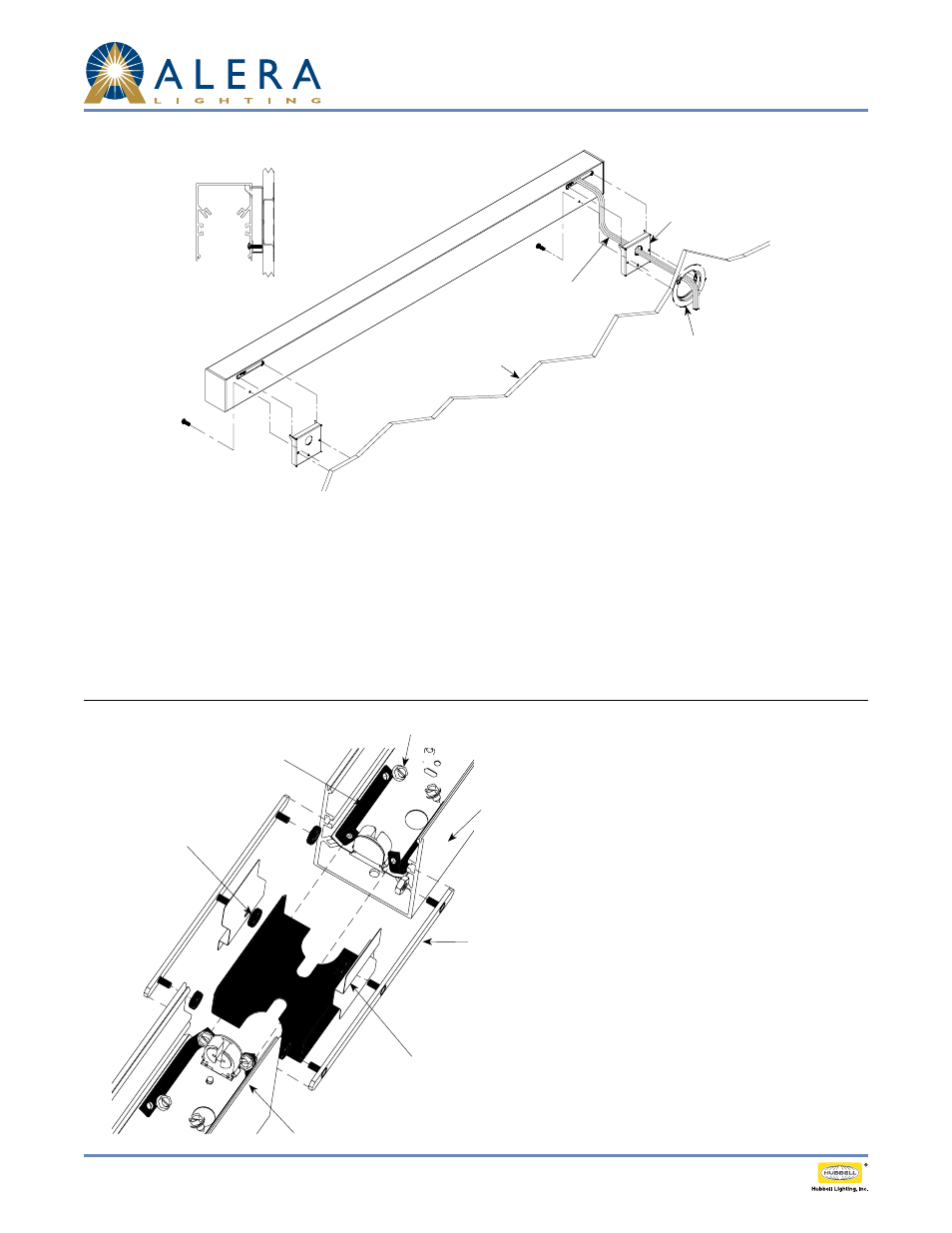
inStallation inStructionS
1. Mount wall brackets orienting the bracket ears upward. At feed location pass supply leads through large hole in bracket.
2. Remove fixture shielding (lens, baffle, louver, etc.)
3. Remove end caps assemblies by disengaging wire form from slot in electrical tray.
4. Remove electrical tray from fixture.
5. Mount fixture housing to wall brackets by rotating the bottom of the housing slightly outward passing the wall bracket ears (and supply
leads) through the slot near the top of the housing. Rotate the housing into a vertical position so the back of the housing is flush with the
wall bracket and install bracket mounting screw from the inside bottom of the housing.
6. Connect supply leads to electrical tray components; black to black, white to white and green to ground according to code requirements.
7. Remount electrical tray.
8. Reinstall end cap assemblies.
9. Reinstall shielding.
Wall
Electrical supply into fixture
(2) Mounting Brackets
Plaster ring mounted in wall by others
1. Attach connector brackets to reflector on each
housing using the #8 screws. Ensure the angles are in
the same direction on each housing. (4 total)
2. Insert Top Light Seal halfway into one of the Housings.
3. Insert Aligner with Pem Studs into the "C" channel
slots on one of the housings (2 total)
4. Use the #8 nuts to secure the aligner to the housing
A. (2 total)
5. Attach each Light Seal to the Aligner using the #8
nuts. Do not tighten the nut at this point. (2 total)
6. Butt Housing B against Housing A while engaging Top
Light Seal and electrically connecting in-row wiring.
7. Engage the connector brackets with the screws
provided. Tighten the screws until the housings are
pulled together.
8. Secure the Aligner in Housing B with #8 nuts provided
and tighten.
9. Tighten the nuts on the side light shields.
connection inStructionS
Housing A
Housing B
Aligner w/ Pem
Studs (2 places)
#8 Nuts
(6 Places)
Light Seal (2 Places)
#8 Screws (6 places)
Conn Brackets (4 Places)