Mdi, mdia cable mount, Technical installation data – Alera Lighting MDI, MDIA Cable Mount User Manual
Page 2
© 2009 Alera Lighting, a division of Hubbell Lighting, Inc. Because of continuing product improvement programs, Alera Lighting reserves the right to change specifications
without notice. 701 Millennium Blvd. Greenville, SC 29607 / Tel 864.678.1000 / Tech Support 864.678.1580 / Website www.aleralighting.com
Page 2/2 Rev. 09/29/09
BeAMS / MDI MDIA CM TID
MDI, MDIA CAble Mount
Technical Installation Data
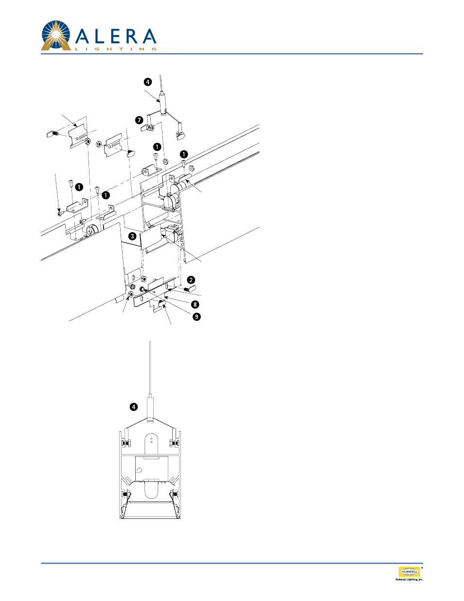
ConneCtIon InStruCtIonS
Attach Top Mounting Brackets to the top of each
1.
housing as shown using 8-32 screws provided.
Slide a Flanged Mounting Stud into each lower track
2.
in each housing and one in each upper track on
Housing B. (6 total)
Insert Middle Light Seal halfway into one of the
3.
Housings.
Attach cable hanger assembly by sliding weld studs
4.
into upper track on Housing A.
Butt Housing B against Housing A while engaging
5.
Middle Light Seal and Top Mounting Brackets, and
electrically connecting in-row wiring.
Connect Top Mounting Brackets on top of each
6.
housing using #8 screws and nuts provided and
tighten.
8. Attach both Top Light Seals to respective Flanged
7.
Studs using #8 nuts provided, slide assembly down
track engaging Cable Mounting Bracket through slot
in each Light Seal and tighten nut.
Attach each Bottom Light Seal to an Aligner using
8.
the 8-18 × ¼ sheet metal screws provided using the
center hole in the seal.
Engage slots in each Aligner assembly with Flanged
9.
Studs in lower track. Secure with #8 nuts provided
and tighten.
Housing B
Housing A
Top Light Seal
(2 Places)
Cable Hanger Assembly
Top Mounting Bracket
(4 Places)
Middle Light Seal
Bottom Light Seal (2 Places)
Aligner (2 Places)
8-18 × ¼ Screw
(2 Places)
8 × 32 Thread
Cutting Screw
(6 Places)
Mounting Nut & Washer
(6 Places)
Flanged Stud (6 Places)
CAble hAnger CroSS SeCtIon