F4 wall mount, Technical installation data, Installation instructions – Alera Lighting F4 - Wall Mount User Manual
Page 2: Contact factory for pattern dimensions
© 2009 Alera Lighting, a division of Hubbell Lighting, Inc. Because of continuing product improvement programs, Alera Lighting reserves the right to change specifications
without notice. 701 Millennium Blvd. Greenville, SC 29607 / Tel 864.678.1000 / Tech Support 864.678.1580 / Website www.aleralighting.com
Page 2/2 Rev. 09/04/09
BeAMS / F4 WM TID
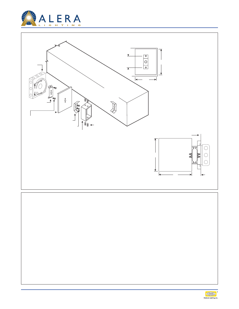
F4 Wall Mount
Technical Installation Data
Installation Instructions:
1. Attach
wall bracket to plaster ring
using plaster ring screws (pull service
leads thru center hole).
2. With
R.H.M screws attach wall plate
and
mounting cleat to wall bracket.
3. Using socket
set screws secure
support arm to wall plate by driving
screws behind the flange of
mounting
cleat.
4. Pull service leads into fixture and
secure fixture to
support arm in same
manner as step (3) above.
5. Make service lead connection to
ballast leads and ground wire and
replace
reflector and lens or louver.
Fixture turned 90° to show
mounting cleat on back side
(factory installed).
51/2"
23/4"
Contact factory for pattern dimensions.
Mtg. hole 2 3/4".
Hole centers match
standard plaster ring
on 4" square box.
41/2"
Junction
box and
plaster ring
by installing
contractor.
Screws to plaster
ring by installing
contractor (On non-
feed brackets sub. 1/4
diameter lag bolts).
Wall Bracket
114871
Wall Plate
112867- color
R.H.M Screws
10-24 × 1/2
Support Arm
113033-color
Mounting Cleat
114869
Set Screws
1/4-20 × 1/2
rec. soc. headless
13/4"
Wall Line
Wall Bracket
Minimum length 13/4"
furnished as standard.
Finish match painted
fixture. Matte black
for plated fixtures.
6"
6"